


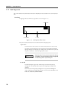

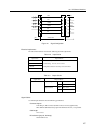
12.1 UPS Control Interface
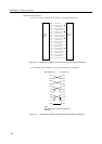
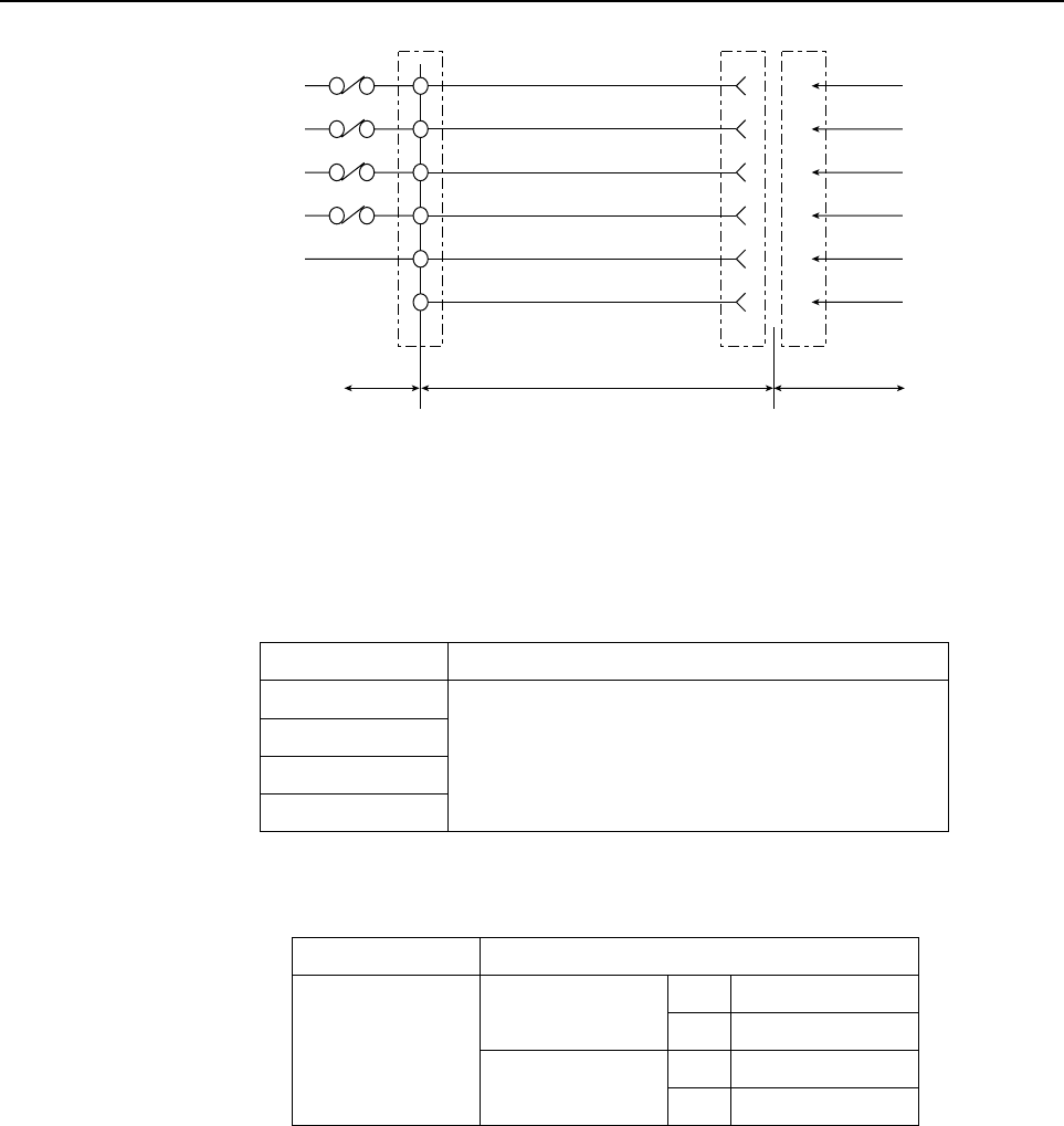
*BPS
*BTL
*UPSON
*ACOFF
SG
ER
BPS
BTL
UPSON
ACOFF
SG
ER
GP 7000Interface cableUPS
6
7
8
9
5
1
Figure 12.1 Signal Configuration
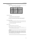
Electrical requirements:
The UPS control interface must meet the following electrical requirements:
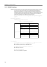
Table 12.2 Input Circuits
Signal names Input conditions
*BPS
*BTL
*UPSON
*ACOFF
* Dead-front relay contacts
* Contact rating: 12 V DC, 10 mA or more
* Gold plated contacts or lead relays are recommended.
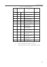
Table 12.3 Output Circuits
ER Output voltages
Output currents
3.76 V to 5.5 v
0. to 0.4 v
max. -4 mA
max. 4 mA
Signal names Output conditions
VOH
VOL
IOH
IOL
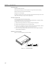
Signal Cables
Use shielded pair cables that meet the following specifications.
Connector shapes:
D-SUB 9-pin, Male connector (Female connector on the equipment side)
DEU-9PF-FO (Manufactured by Japan Aircraft Electronics Inc.) or equivalent
Cable length:
10 m or less
DC resistance:(per pair, both ways)
400 ohm/km or less
147