


CHAPTER 12 External Interfaces
12.1 UPS Control Interface
Overview The UPS control interface is used to perform temporary data saving processing. In this processing, a
reserved interruption for software occurs when the uninterruptible power supply (UPS) is used to
backup a power failure in the commercial AC power supply. In addition to this type of UPS control
interface, there are several other UPS units that use the general-purpose interface such as RS232C.
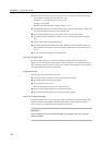
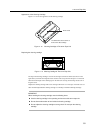
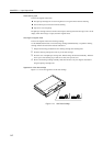
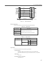
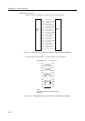
Connecting interfaces
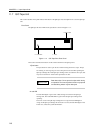
The configurations and definitions of the signal lines to be connected to the UPS system are shown
below. Do not use pin numbers unspecified below to connect to the UPS system.
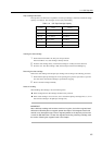
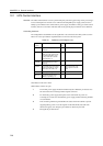
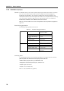
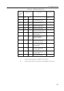
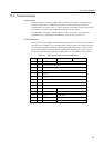
Table 12.1 Definitions of UPS Signal Lines
Signal Definitions Pin Remarks
names Nos.
BPS Signal indicating faulty UPS 6 Enabled with ON.
conditions
BTL Signal indicating that the UPS 7 Enabled with ON.
battery level has lowered and
that ineffectual battery char
ge may result after a certain
period of time (*1)
UPSON Signal indicating the UPS is 8
operating
ACOFF Signal notifying power failure 9 When power fails: ON
in the commercial AC supply When power is normal:
connected to the UPS (*2) OFF
SG System ground signal 5
ER (*4) Signal indicating the main 1
cabinet is operating (*3)
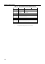
ON indicates contacts are closed.
OFF indicates contacts are open.
*1 The normal power supply should be maintained by the UPS battery for at least 10 to
60 seconds after the connecting interface signal is turned on.
*2 For momentary power supply interruption of the commercial AC power not
exceeding two seconds, the normal battery power supply without activating ACOFF*
is recommended.
*3 This connecting interface signal identifies the status of the main cabinet to prevent
supplying battery power in case the signal is in the OFF (LOW) state (the main
cabinet is stopped), even though a power failure is detected by the UPS.
*4 ER signal may be left unused.
146