


CHAPTER 10 Expansion File Unit (GP7B7FU1xx)
status LED
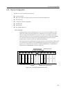
A POWER LED and a CHECK LED are installed on the front of the cabinet. The POWER LED
indicate if the power is on or off. And, the CHECK LED indicates if there is any hardware errors or
not. The CHECK LED operates as described in the Table 10.1 .
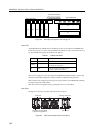
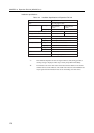
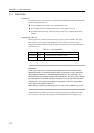
Table 10.1 CHECK LED Status
Indication Remarks
No errors
Identifying a device Activated when a maintenance command is used
to identify the target device.
Error The cause of the error will be a power
failure, or abnormal fan rotation.
State
Off
Blinking
On
When a power supply unit or fan unit is failed, the CHECK LED is lighted steadily. And, if a disk
unit fail, its FAULT LED is lighted by software command to identify the faulty disk unit.
When a FAULT LED is lighted up according to hot-swap procedures, the CHECK LED is lighted
steadily to identify an Expansion Disk Cabinet.
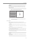
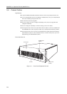
Disk units can be hot-swappable easily by opening the front cover of the cabinet.
Rear Panel
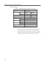
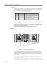
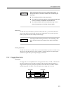
The Figure 10.3 shows the rear panel of Expansion File Unit.
RCI PortService Pin
SCSI IN Connector
( Standard )
SCSI IN Connector
( Option )
SCSI OUT Connector
( Standard )
SCSI OUT Connector
( Option )
AC Power Input
AC Main Line Switch
Figure 10.3 Rear View of Expansion File Unit
The Expansion File Unit doesn’t power on/off by only the main line switch, but it linked to power
on/off of the GP7000F main cabinet. Note that this file unit does not power on if the main line
switch is OFF, even if the GP7000F main cabinet is powered on. Keep the main line switch set to
ON for regular use.
Be sure to set the RCI configuration, which is detailed in Chapter13 , must be set properly when
installing an Expansion File Unit.
The cabinet has 2 pair of SCSI IN/OUT connectors on it. When the cabinet is configured without
expansion (optional) drive bays, a SCSI cable must be connected to the standard SCSI IN connector.
116