


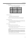


12.2 RS232C Interface
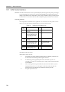
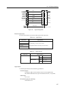
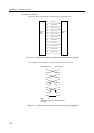
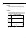
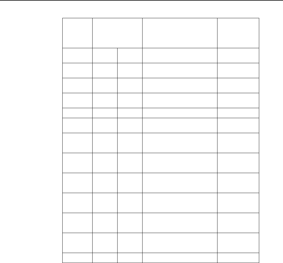
Table 12.5 Definitions of Signal Lines
Signal Pin Nos. on the
names and Voltage levels Description I/O device side
pin Nos.on
the host
side
(DSUB25P)
SD: 2
RD: 3
RS: 4
RS: 4
CS: 5
ER: 20
DR: 6
CD: 8
ST1:24
ST2:15
RT: 17
SG: 7
'0'-off '1'-on TERMINAL-25P
(*1) (*1)
+8 V -8 V GP transmitting data signals
+8 V -8 V GP receiving data signals
-8 V +8 V Transmission request signal
when the GP transmits the data
-8 V +8 V Transmission request signal
-8 V +8 V Request to transmit when the
I/O device sends out the data
-8 V +8 V Status signal to indicate
whether or not the host is
ready for operation
-8 V +8 V Status signal to indicate
whether or not the I/O device
is ready for operation
-8 V +8 V Indicates that the I/O device
receives the signal from the
connected system normally
+8 V -8 V Reception timing for the I/O
device to be supplied with the
data from the GP
+8 V -8 V Transmission timing for the
I/O device to supply the GP
host with the data
+8 V -8 V Transmission timing for the
I/O device to supply the GP
host with the data
-- -- Used as a signal return line.
3
2
5
5
4
6
20
5-8(*2)
24
15
17
7
*1 Indicates the data signal logic or ON/OFF of the control line.
*2 Indicates the pin numbers short-circuited on the TERMINAL side connector.
149