


9.2 Device Configuration
9.2 Device Configuration
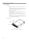
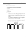
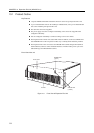
This file unit consists of the following components.
Rack mount cabinet
Basic power supply and expansion option power supply (for redundant configuration)
DC-DC converter
Cooling fans (redundant configuration)
SCSI-BP boards
Interface board
Hot-swappable disk drives
Disk configuration
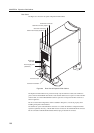
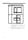
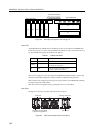
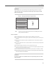
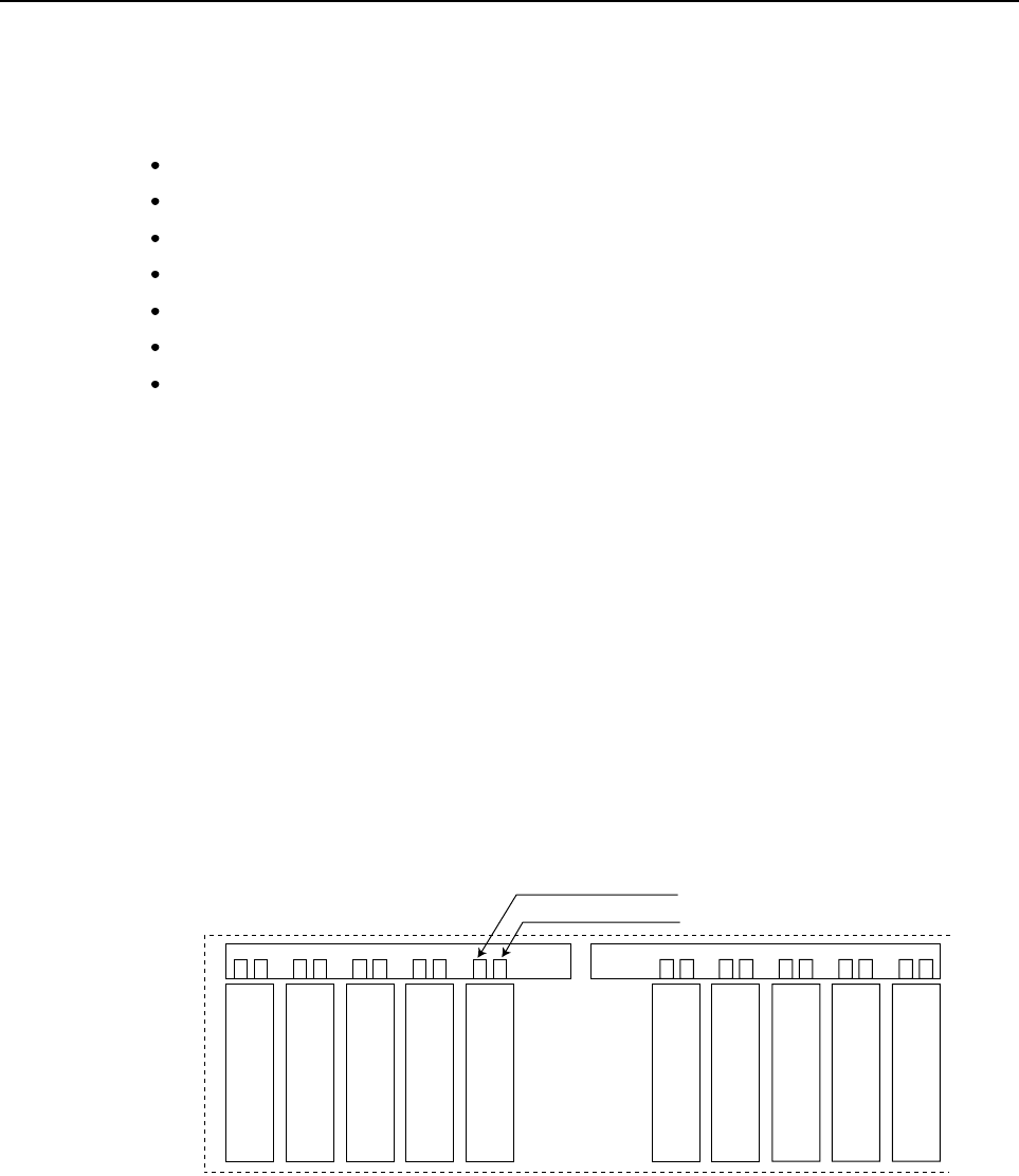
Opening the unit’s front cover, Figure 9.2 and Figure 9.3 shows the drive bays Figure 9.2 . Shows
a Basic SCSI Unit and an File Unit Expansion Kit bay configuration. Figure 9.3 shows a Basic
SCSI unit (SCSI bays #1~#5) and an Tape Unit Bay Kit (tape bays #1 and #2) bay configuration.
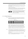
The Basic SCSI Unit (SCSI bays #1~#5) and the File Unit Expansion Kit (bays #1~#5) or the
Tape Unit Bay Kit (tape bays #1 and #2) can be connected to the main processing unit by separate
SCSI busses.
Up to 10 UltraSCSI disk units (5 UltraSCSI disk units is the standard) can be accommodated by
installing an File Unit Expansion Kit to this unit. Or, by installing an Tape Unit Bay Kit, a
maximum of any two: 8 mm, DAT, or QIC tape unit can be added.
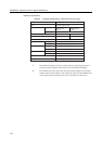
Each interface board has a POWER LED. If a FAULT LED and an ACTIVE LED of a disk bay that
has a disk drive doesn’t light up, check the POWER LED on the interface board in the cage if it is
light up or not. A failed unit can be isolated by checking this POWER LED, a ACTIVE LED, a
FAULT LED, and a POWER LED on the power supply unit.
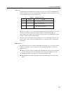
#1 #2
#3
#4 #5 #1 #2
#3
#4 #5
ACTIVE LED (Green)
FAULT LED (Amber)
Basic SCSI Unit
File Unit Expansion Kit
Figure 9.2 Drive Bays of Expansion File Unit Type-2
107