3600 Printer Maintenance Manual
A-6
Motor Driver
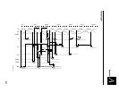
The motor driver circuit of the 3600 consists of ICs U2, U21, U17, and U19;
discreet parts Q16, Q1, Q3, Q4, Q6, Q11, Q12, Q13, Q14; and associated diodes,
resistors, and capacitors. The eight D-MOS FETs make up a dual full-bridge
motor driver. There are four FETs to drive each motor phase. There are two
FETs at each end of each motor phase.
When a phase is driven or turned on, one FET on each end of a phase is turned
on. One of the FETs will be a high side FET putting 50 volts on one end of the
winding. The other FET will be a low side FET putting zero volts on that end of
the winding.
When the motor is running the windings are being excited first with 50 volts on
one end, and then the 50 volts on the other end. At no time are both FETs on
the same end of a winding on at the same time.
When a winding is turned on, the current is first monitored and then controlled
by turning the FETs on and off at a high rate. This is called pulse width
modulation. The current in the winding is monitored measuring the voltage
across the sense resistors R18, R22, R97, and R99. These voltages are called
sense_A1 and sense_B1. These voltages are inputs to U2. U2 is a comparator
that compares a reference voltage (voltage at U2 pins 2 and 6) to the voltages
sense_A1 and sense_B1. When these voltages become greater than the sense
voltage the associated out put of U2 switches from low to high. This voltage is
fed into the GAL U21 and then to the appropriate driver IC U17 or U19 which
turns the associate FET off. The off time during this pulse width modulation
cycle is constant and controlled by the C109, R127 for sense_A1 or C42, R137
for sense_B1.
The reference voltage on pins 2 and 6 of U2 is established by the pulse width
modulation input M5. This is an input from the microprocessor to Q15 through
R108. The duty cycle of this signal controls the reference voltage input to U2.
The magnitude of this voltage establishes the magnitude of the current in
motor windings.
Other inputs from the microprocessor to the GAL U21 circuit are M1, M2, M3,
and M4. These inputs control the stepping of the motor. They go into the GAL
where they are decoded and fed into the driver ICs U17, U19 which turn the
FETs on and off.
Reset is the last input to the motor driver circuit. U19 pin 3 is high when reset
is applied to the DISABLE input of U17. This action ensures that all the FETs
are held in the off condition to control start up and shut down transients.


