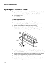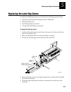
Remove and Replace Procedures
5-11
5
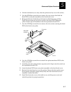
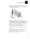
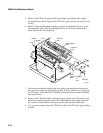
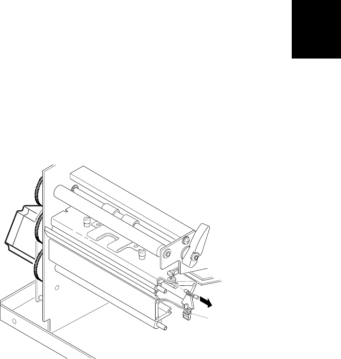
5. Disconnect the label mark sensor cable from the main PCB, remove the
cable from the two plastic clips, and push it through the cutout in the main
deck plate. Slide the sensor out from the extrusion. Remove the cable from
the plastic cable clip on the extrusion.
3600M.049
Label mark
sensor
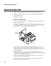
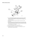
6. Insert the new label mark sensor into the extrusion. Route the cable
through the plastic cable clip on the extrusion and through the cutout in the
main deck plate, and then plug it into the main PCB. Secure the cable in
place by inserting it into the two cable clips. Any slack in the cable should
be arranged between the sensor and the cable clip on the extrusion. There
should be no slack cable on the electronics side of the printer. Make sure
the cable is secure and not contacting any moving parts.
7. Reassemble the tear bar and bar support and install the lower outboard
plate, capturing the tear bar, liner drive roller, and platen roller.
Note: Use the roller alignment tool during reassembly for proper alignment of the
outboard plate.
8. Reattach the front bezel cover. Ensure that the media access door operates
properly (snaps firmly shut) after the front bezel cover is installed.
9. Reload media (and ribbon if used) and lower the printhead.
10. Install the electronics cover, the media cover, and the power cord, and
check the printer for proper operation.


