3600 Printer Maintenance Manual
5-8
Replacing the Main PCB
To replace the main PCB, you will need the following parts and tools:
• 3600 main PCB assembly, Intermec Part No. 061591S-005 or 06159E-005
• ESD grounding strap
• #2 Phillips screwdriver
To replace the main PCB assembly
1. Switch off the printer power and remove the power cord, the media cover,
and the electronics cover.
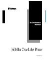
2. Unplug all of the cables from the main PCB and remove the seven screws
securing the main PCB to the printer to remove the main PCB. Do not place
the printer on its side as this may disturb alignments.
Power
Intermec
3600
Alert
Feed/Pause
Empty/Pause
J9
3600M.046
Main PCB
assembly
3. If the main PCB you are replacing has the 512K SRAM memory expansion
chip, verify that the new main PCB is similarly equipped. If it is not,
carefully unplug the existing 512K chip and plug it into the new main PCB
before installing it.
4. If the main PCB you are replacing has a Kanji/Katakana option PCB
installed, use the next procedure to relocate the Kanji/Katakana option PCB
to the new main PCB before installing it.
5. Install the new main PCB, securing it with the seven screws removed in
Step 3, and connect all of the cables.
6. Install the electronics cover, the media cover, and the power cord, and
check the printer for proper operation.