3600 Printer Maintenance Manual
A-10
Communications Interface
The communications interface for the 3600 follows the Intermec Standard Data
Connector standard. J1 is a 25 pin D-sub connector that supports both RS-232
and RS-485 interfaces. U1 is the RS-485 driver/receiver and U22 and U4 are the
RS-232 driver and receivers. To further enhance the interface to support
DTR/RTS flow control, the DTR pin is driven with the PIN 14 signal. This
arrangement allows the use of standard cables for hardware flow control,
which enables the user to use commands such as the DOS COPY command
from any PC. Zero ohm resistors have been incorporated into the RS-232 driver
outputs so that the previous configuration or other configurations are possible.
A/D Converter
The Motorola MC145041 A/D converter is an 11-channel, 8-bit, serial A/D
converter. The reference is set to +5V. Seven of the eleven channels are used:
Channel Function
0 Label gap sensor
1 Darkness adjust
2 Printhead thermistor
3 Label mark sensor
4 +40V
5 Printhead voltage, +24V
6 Label taken sensor
The A/D converter is continuously communicating with the MC68332 through
the SPI. It receives conversion commands and channel addresses while sending
back results from the previous command. The clock rate for the MC145041 is
1 MHz.
DIP Switches
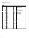
The 3600 has 16 DIP switches to provide configuration and test and service
operation.
ASIC and I/O Option Interface
The 3600 uses an Intermec designed thermal compensation ASIC. This ASIC
handles the loading of the printhead to implement the dot-by-dot thermal
management scheme.
Address/Data Multiplexor
Since both the ASIC and the I/O option interfaces are designed to interface
with a processor that has multiplexed address and data, it is necessary to
multiplex the address and data from the MC68332. ICs U14 and U15 are used
to route address or data to the AD (0:7) bus.


