


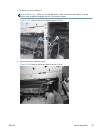
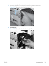
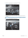
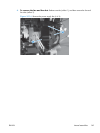
4. Disconnect two connectors (callout 1) on the back side of the assembly.
Figure 2-110 Remove the RD sensor assembly (4 of 6)
1
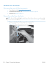
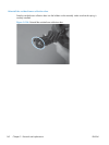
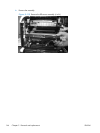
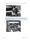
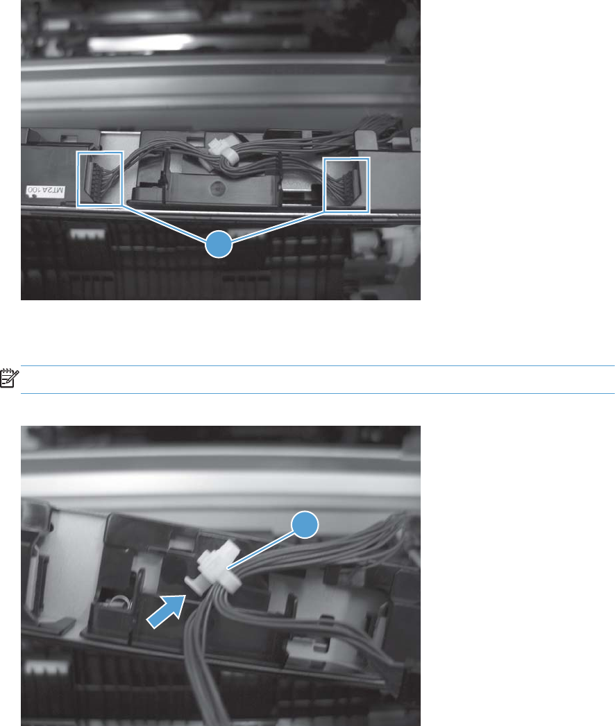
5. Push in on the locking tab to release the retainer (callout 1), and then separate the retainer from
the assembly.
NOTE: The retainer remains attached to the wire harness, and disengages from the assembly.
Figure 2-111 Remove the RD sensor assembly (5 of 6)
1
ENWW
Internal assemblies
145