


6-47Removal and Replacement
OVERDRIVE SUPPORT ASSEMBLY REMOVAL
To remove the overdrive support assembly, perform the following procedure:
1. Remove the window assembly.
2. Remove the left and right endcovers.
3. Remove the encoder strip.
4. Remove the front panel assembly.
5. Remove the cutter assembly.
6. Remove the bail assembly.
7. Remove the service station assembly.
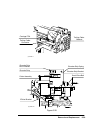
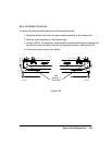
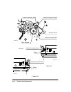
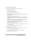
8. Using a TORX T-15 screwdriver, remove the gear shoulder screw that secures the
overdrive cluster gear to the left sideplate. See Figure 6-31.
9. Pull the overdrive cluster gear out of the plotter. The gear should move freely when
properly installed.
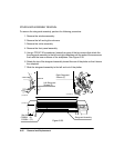
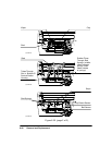
10. Using needle-nose pliers and a small standard screwdriver, remove the clutch re-
taining ring that secures the overdrive assembly clutch to the overdrive assembly
shaft.
11. Remove the overdrive assembly clutch and the two Teflon washers behind it from
the overdrive assembly shaft.
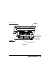
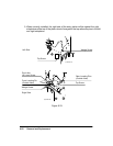
12. Using a TORX T-10 screwdriver, remove the screws that secure the left and right
ends of the overdrive support assembly to the overdrive support assembly mounts.
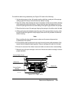
13. While lifting the right end of the overdrive support assembly slightly, rotate the bot-
tom end of the overdrive assembly to fit in the cutter enclosure channel. Lift the left
end slightly, and slide the overdrive support assembly to the right until the overdrive
shaft clears the left sideplate.
14. Lift the overdrive support assembly clear of the plotter.