


6-8 Removal and Replacement
INTERCONNECT PCA REMOVAL
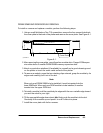
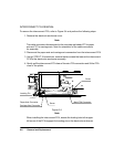
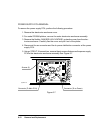
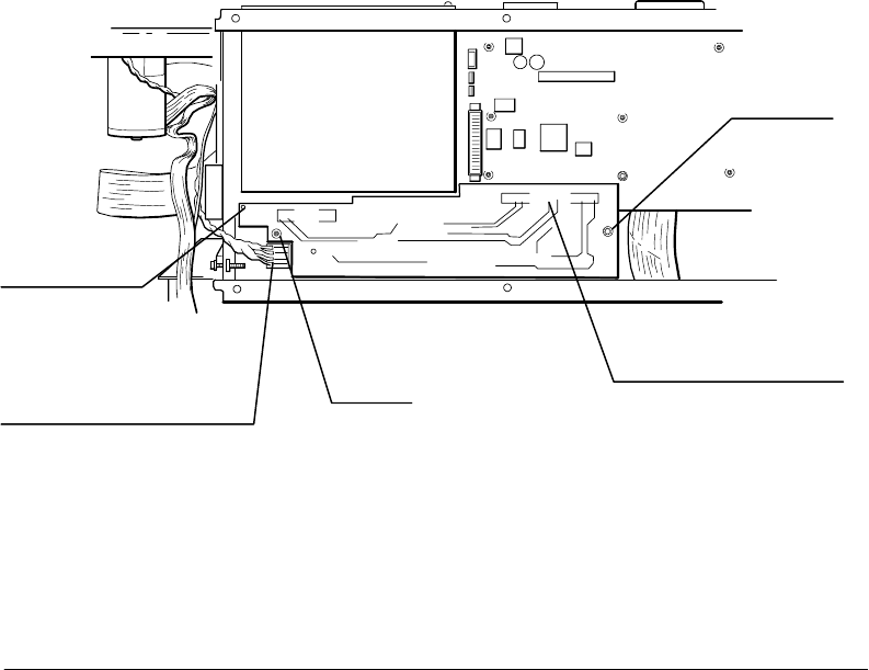
To remove the interconnect PCA, refer to Figure 6-4 and perform the following steps:
1. Remove the electronic enclosure cover.
Note
The cable connectors disconnected in the next step are labeled ªPº for paper
axis and ªCº for carriage axis. Note the orientation of the cable connectors
for assembly.
2. Disconnect the paper axis and carriage axis connectors from the interconnect PCA.
3. Using a TORX T-10 screwdriver, remove the two screws that secure the interconnect
PCA to the electronics enclosure assembly.
4. Gently pull the interconnect PCA clear of its main PCA connection and lift the PCA
clear of the plotter.
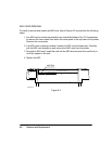
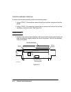
Figure 6-4.
Locating Pin
Screw
Screw
Paper Axis Connector
Carriage Axis Connector
Main PCA Connector
(C)C2858-46
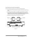
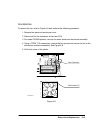
Note
When installing the Interconnect PCA, ensure the locating hole in the upper
left corner of the PCA engages the locating pin on the electronics enclosure.