


6-4 Removal and Replacement
REQUIRED TOOLS
Tools required to disassemble and repair the HP DesignJet 650C plotters are listed in
Table 6-1.
Item Size
Torx Screwdriver with bits T8, T9, T10, T15, T20, T25, T30
Screwdriver, flat-blade Small
Nut Drivers 1/4 in., 3/16 in., 5.5 mm (or 7/32 in.)
Pliers, needle-nose Medium
Wrenches, socket or open-end 3/8 in., 9/32 in. (or 7mm)
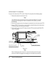
REPAIR PROCEDURES
Unless otherwise specified, reassembling should be performed in the reverse order of disas-
sembly. Be sure to read and perform any precautions given in the procedures.
Certain repairs will require you to perform calibration procedures to return the plotter to cer-
tain performance parameters or ensure proper operation after repairs are completed. Refer to
the table of calibration requirements in Chapter 7 and perform the calibrations listed after the
appropriate repairs are made.
Many repair procedures require other assemblies to be removed to perform the desired repair.
Assemblies to be removed will be referenced in the procedure. To remove those assemblies,
refer to the appropriate removal procedures in this chapter.
W A R N I N G