


6-53Removal and Replacement
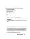
DRIVE ROLLER ASSEMBLY REMOVAL
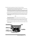
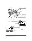
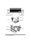
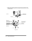
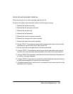
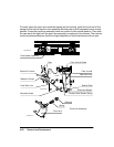
While removing the drive roller assembly, see Figure 6-34.
To remove the platen roller assembly, perform the following procedure:
1. Remove the window assembly.
2. Remove the left and right endcovers.
3. Remove the encoder strip.
4. Remove the bail assembly.
5. Remove the overdrive support assembly.
6. Remove the carriage drive motor assembly.
7. Remove the paper drive motor assembly.
8. Using a TORX T-10 screwdriver, remove the two screws that secure the drive roller
worm gear to the drive roller shaft. See Figure 6-34.
9. Pull the drive roller worm gear clear of the drive roller shaft.
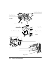
10. Using a TORX T-15 screwdriver, remove the two drive roller collar screws that at-
tach the drive roller assembly axial bias plate to the inside of the right sideplate.
11. Using a TORX T-20 screwdriver, remove the three screws that attach the paper mo-
tor mount to the right sideplate.
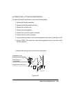
12. Using a TORX T-15 screwdriver, remove the screw that attaches the media director
to the chassis assembly and remove the media director.
13. Using the manual lever, raise the pinch arm assembly and remove the drive roller
assembly from the plotter.