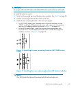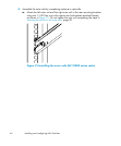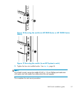
6. Identify the screw holes to be used on the inner rails designed for the switch:
• To attach the inner rails to the SAN Switch 2/32 use the screw holes
marked 32.
• To attach the inner rails to the 4/8, /16 and 4/32B SAN Switches, use five
screw holes marked 8, and the plenum requires one screw hole marked 8
and one screw hole marked 16,asshowninFigure 15 on page 48.
• To attach the inner rails to the 4/32 or 4/64 SAN Switch, use the screw
holes marked 16,asshowninFigure 16 on page 48.
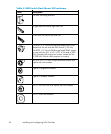
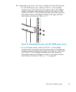
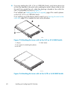
7. Assemblethetwoinnerrailstothedeviceusingtheappropriatenumberofscrews
(see Table 5):
• For the 4/8 and 4/16 SAN Switches, secure each inner rail (one on each
side) to the switch using seven #8-32 x 5/16-inch Phillips pan-head SEMS
screws, as shown in Figure 15 on page 48.
• For the 4/32 SAN Switch, secure each inner rail (one on e ach side) to the
switch using five #8-32 x 5/16-inch Phillips pan-head screws with thread
lock, as shown in Figure 16 on page 48.
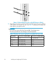
• Forthe4/64SANSwitch,secureeachinnerrail(oneoneachside)to
the switch using five #8-32 x 5/16-inch Phillips pan-head SEMS screws,
as shown in Figure 16 on page 48.
• For the 4 /32B SAN Switch, secure each inner rail (one on each side)
to the switch using six #8-32 x 5/16-inch Phillips pan-head screws with
thread lock.
NOTE:
For integration in a c abinet, tighten the #8-32 x 5/16-inch Phillips
pan-head SEMS screws and torque between 6 and 8 inch-pounds.
SAN Switch installation guide
47


