Scale: 1/4" = 1"
MRO25017a
2
1
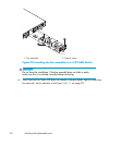
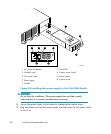
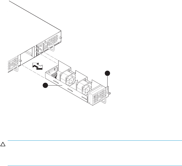
1. Fan assembly
2. Captive screw
Figure 32 I
nstalling the fan as sembly in a 4/32 SAN Switch
CAUTION:
Do not forc
e the installation. If the fan assembly does not slide in easily,
make sure that it is oriented correctly before continuing.
6. Verify that the Fan Status LED does not display a steady amber light for more than
five seconds, which indicates a fault (see Table 19 on page 97).
98
Installing field-replaceable units


