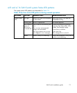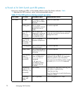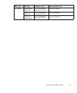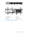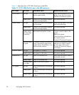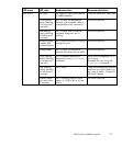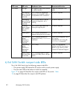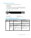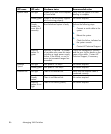
Table 14 describes the 4/32 SAN Switch nonport side LEDs.
Table144/32SANSwitchnonportsideLEDpatterns
LED name
LED color Hardware status Recommended action
No light Power supply is not receiving
powerorpowerisoff.
Verify that the power supply is on
andseatedandthepowercordis
connected to a functioning power
source.
Steady green Power supply is o
perating
normally.
No action requir
ed.
Power Supply
Status
Steady amber
(for more than
5 seconds)
Powersupplyfaultforoneof
the following reasons:
Power cable is disconnected.
Power supply is off.
Power supply has failed.
Try the following:
Check the power cable connection.
Verify that the power supply is
powered on.
Replace the power supp ly.
No light Fan assembly is not receiving
power.
Verify that the fan assembly is seated
in the switch.
Steady green Fan assembly is operating
normally.
No action required.
Fan Status
Steady amber
(for more than
5 seconds)
Oneormoreofthefansinthe
fan assembly failed or the fan
FRU was disabled by the user.
Verify that the fan FRU is enabled.
If the fan FRU is enabled, the FRU is
faulty and should be replaced.
4/64SANSwitchportsideLEDs
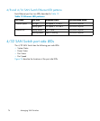
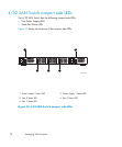
The 4/64 SAN Switch integrates the following port side LEDs:
• System Sta
tus LED
• Power Status LED
• Two Ethernet Port LEDs
• One Port S
tatus LED
• Port Speed LED for each p or t on the switch. These LEDs are displayed below
each pair of Fibre Channel ports. The LEDs are located in the array in the same
relativ
epositionsastheports.
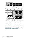
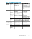
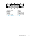
Figure 26 onpage80identifiestheLEDsontheportsideoftheswitch. Table
15 onpage81describestheportsideLEDpatterns.
SAN Switch installation guide
79


