


46 Hardware Maintenance Manual: xSeries 220
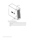
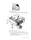
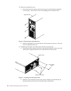
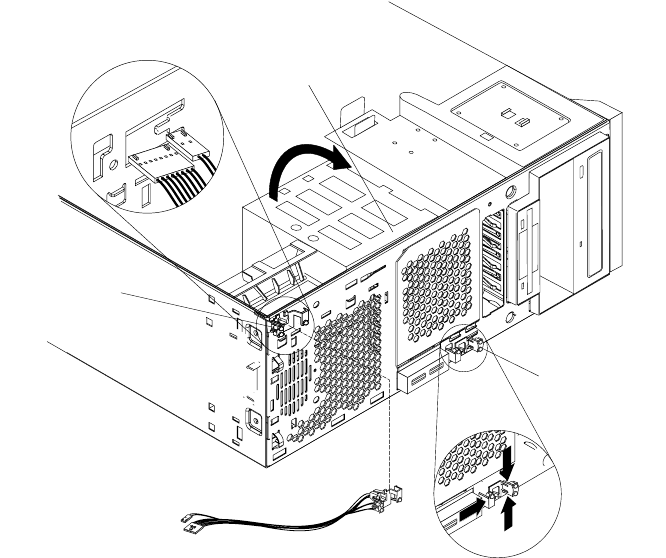
c. To remove the power-switch and LED panel, press in on the tab on the left
side of the panel; then, squeeze the top and bottom of the right-side of the
panel and carefully pull the panel away from the system.
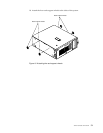
Figure 6. Relocating the power-switch and LED panel
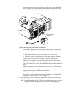
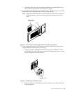
d. Note where the power-switch and LED panel cable connects to the system
board; then, carefully disconnect the cable from the system board.
Notes:
1) Some cables might have two connectors for you to disconnect.
2) Refer to the system service label for system board connector locations.
e. Gently pull the cable through the opening on the front of the system.
Note: The cable might be routed through a cable clamp in some systems.
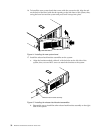
f. Carefully push the cable through the opening in the new location on the
system; then, connect the cable to the system board where you disconnected it
earlier.
Note: If your cable has two connectors, make sure that you connect both of
them to the system board.
g. Align the power-switch and LED panel with its new location; then, carefully
snap the panel into place on the front of the system.
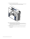
h. Lower the drive cage back to its normal position; then, re-install any hot-swap
drives that you removed in the appropriate drive bays (see “Installing a hot-
swap hard disk drive in bay 5, 6, or 7” on page 72).
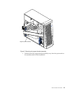
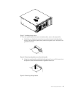
10. Align the top cover with the top of the system; then, slide it toward the front of
the system until the cover snaps into place.
Note: Ensure that the tabs on the back of the cover fit into the slots on the back of
the system. Be sure that the front edge of the cover is flat against the
system.
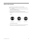
Tower-orientation
for switch
Rack-orientation
for switch
Drive cage