


Installing options 83
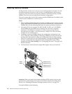
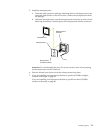
a. Insert a small, flat-blade screwdriver into the tab on the fan-sink retainer
(clip).
b. Press down and in with the screwdriver handle to remove the fan-sink
retainer from the fan sink.
c. Firmly grasp the fan sink and lift it off the microprocessor. Store the fan sink
in a safe, clean place with the bottom side up. The thermal material on the fan
sink must stay clean if you intend to reuse the fan sink in the future.
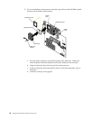
d. Disconnect the fan-sink power cable from the appropriate connector on the
system board:
• If you are removing the microprocessor from connector U11, disconnect
the fan-sink power cable from connector J2.
• If you are removing the microprocessor from connector U12, disconnect
the fan-sink power cable from connector J3.
7. Lift up the release lever and remove the microprocessor from the connector. Store
the microprocessor in a static-protective bag for possible future use.
8. If you are installing a new microprocessor, go to “Installing a microprocessor” on
page 78.
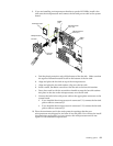
9. If you are not replacing the microprocessor:
a. Reinstall the terminator card in the empty microprocessor connector.
b. Press the release lever down to lock the terminator card into place.
c. Remove the VRM from the appropriate VRM connector:
• If you removed the microprocessor from connector U11, press down on
the latches on either side of connector J12, and remove the VRM from
connector J12.
• If you removed the microprocessor from connector U12, press down on
the latches on either side of connector J42, and remove the VRM from
connector J42.
10. If you have other options to install or remove, do so now; otherwise, replace the
support bracket assembly; then, go to “Installing the cover”.
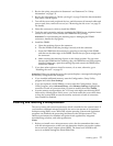
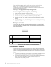
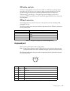
Installing the bezel
The following illustration shows how to install the bezel.
Note: The illustrations in this document might differ slightly from your hardware.
Do the following to install the bezel:
1. Insert the two tabs on the bottom of the bezel into the matching slots in the server
chassis.
2. Push the top of the bezel toward the server until the two tabs at the top of the
bezel snap into place.
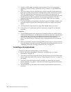
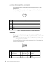
Installing the cover
The following information describes the cover installation procedure.
Note: The illustrations in this document might differ slightly from your hardware.