


78 Hardware Maintenance Manual: xSeries 220
2. Obtain an SMP-capable operating system (optional). For a list of supported
operating systems, see http://www.ibm.com/pc/compat/ on the World Wide
Web.
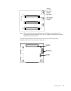
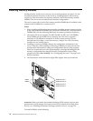
3. The server comes with one microprocessor, which is installed in microprocessor
connector U12 (the microprocessor connector that is closer to the power supply).
This is the startup (boot) microprocessor. If you install a microprocessor in
microprocessor connector U11, that one becomes the startup microprocessor, and
the microprocessor that is installed in microprocessor connector U12 is the
application microprocessor. You must also install a VRM when you install a
microprocessor.
4. If you are installing a microprocessor that has a speed of 933 MHz or higher, you
must also install a fan sink and connect the fan-sink power cable to the system
board.
5. The illustrations in this document might differ slightly from your server.
6. If necessary, see “System board options connectors” on page 55 for connector
locations.
Attention:
• To avoid damage and ensure proper server operation when you install a new or
additional microprocessor, use microprocessors that have the same cache size and
type and the same clock speed. Microprocessor internal clock frequencies and
external clock frequencies must be identical. See the ServerProven list at
http://www.ibm.com/pc/compat for a list of microprocessors for use with the
server.
• When you handle electrostatic discharge (ESD) sensitive devices, take precautions
to avoid damage from static electricity. For details on handling these devices, see
“Handling electrostatic discharge-sensitive devices” on page 136.
Installing a microprocessor
To install an additional microprocessor, do the following:
1. Review the safety precautions in Statement 1 and Statement 5 in “Safety
information” on page 133.
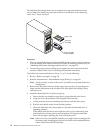
2. Turn off the server and peripheral devices, and disconnect all external cables and
power cords; then, remove the cover (see “Removing the side cover” on page 59
for details).
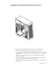
3. Carefully remove the support bracket assembly (see “Removing the support
bracket assembly” on page 61). Store the cover and the support bracket assembly
it in a safe place.
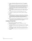
4. Lift the release lever and remove the terminator card from the microprocessor
connector.