


Intel® Xeon® Processor E5-1600/E5-2600/E5-4600 Product Families 137
Datasheet Volume One
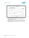
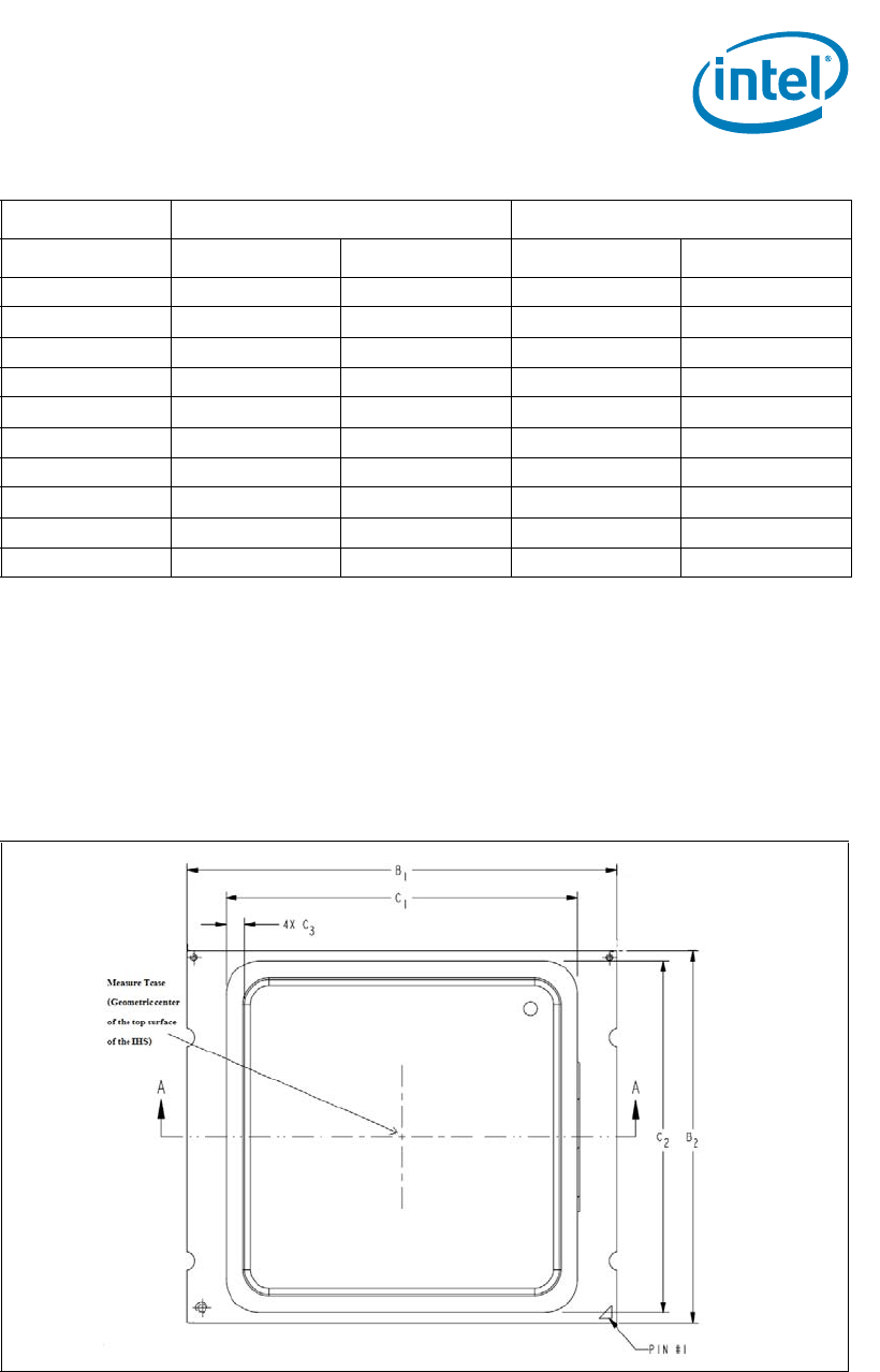
Thermal Management Specifications
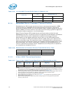
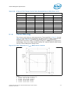
5.1.5 Thermal Metrology
The minimum and maximum case temperatures (T
CASE
) specified in Table 5-2 through
Table 5-30 are measured at the geometric top center of the processor integrated heat
spreader (IHS). Figure 5-32 illustrates the location where T
CASE
temperature
measurements should be made. For detailed guidelines on temperature measurement
methodology, refer to the
Intel® Xeon® Processor E5-1600/E5-2600/E5-4600 Product
Families Thermal/Mechanical Design Guide.
Notes:
1. Figure is not to scale and is for reference only.
2. B1: Max = 52.57 mm, Min = 52.43 mm.
3. B2: Max = 45.07 mm, Min = 44.93 mm.
4. C1: Max = 43.1 mm, Min = 42.9 mm.
5. C2: Max = 42.6 mm, Min = 42.4 mm.
6. C3: Max = 2.35 mm, Min = 2.15 mm.
25 61.0 76.0 64 79
30 62.7 77.7 66 81
35 64.5 79.5 69 84
40 66.3 81.3 71 86
45 68.1 83.1 74 89
50 69.9 84.9 76 91
55 71.7 86.7 78 93
60 73.5 88.5 81 96
65 75.3 90.3 83 98
70 77.1 92.1 86 101
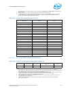
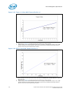
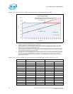
Table 5-30. 8-Core LV70W Thermal Profile Table, Embedded Server SKU (Sheet 2 of 2)
Maximum T
CASE
(ºC)
Maximum DTS (ºC)
Power (W)
Long Term Short Term Long Term Short Term
Figure 5-32. Case Temperature (T
CASE
) Measurement Location