


Intel® Xeon® Processor E5-1600/E5-2600/E5-4600 Product Families 45
Datasheet Volume One
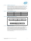
The following conversion formula should be used for encoding or programming the
‘Control Time Window’ in bits [23:17].
Control Time Window (in seconds) = ([1 + 0.25 * ‘x’] * 2
‘y’
) * ‘z’ where
‘x’ = integer value of bits[23:22]
‘y’ = integer value of bits[21:17]
‘z’ = Package Power SKU Time Unit[19:16] (see Section 2.5.2.6.13 for details on
Package Power SKU Unit)
For example, using this formula, a control time value of 0x0A will correspond to a
‘1-second’ time window. A valid range for the value of the ‘Control Time Window’ in
Figure 2-19 that can be programmed into bits [23:17] is 250 mS - 40 seconds.
From a DRAM power management standpoint, all post-boot DRAM power management
activities (also referred to as ‘DRAM RAPL’ or ‘DRAM Running Average Power Limit’)
should be managed exclusively through a single interface like PECI or alternatively an
inband mechanism. If PECI is being used to manage DRAM power budgeting activities,
BIOS should lock out all subsequent inband DRAM power limiting accesses by setting
bit 31 of the DRAM_POWER_LIMIT MSR or DRAM_PLANE_POWER_LIMIT CSR to ‘1’.
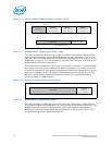
2.5.2.6.10 DRAM Power Limit Performance Status Read
This service allows the PECI host to assess the performance impact of the currently
active DRAM power limiting modes. The read return data contains the sum of all the
time durations for which each of the DIMMs has been operating in a low power state.
This information is tracked by a 32-bit counter that wraps around. The unit for time is
determined as per the Package Power SKU Unit settings described in
Section 2.5.2.6.11. The DRAM performance data does not account for stalls on the
memory interface.
In general, for the purposes of DRAM RAPL, the DRAM power management entity
should use PECI accesses to DRAM energy and performance status in conjunction with
the power limiting feature to budget power between the various memory sub-systems
in the server system.
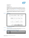
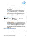
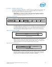
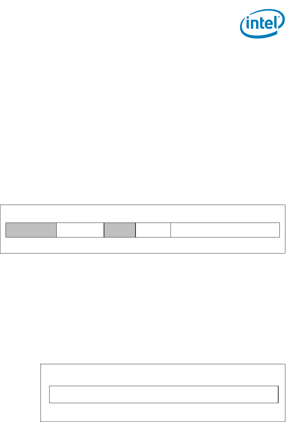
Figure 2-19. DRAM Power Limit Data
DRAM_POWER_LIMIT Data
DRAM
Power Limit
Enable
1523
DRAM Power Limit
14 0
RESERVED
16
Control Time
Window
1731
RESERVED
24
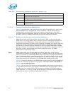
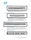
Figure 2-20. DRAM Power Limit Performance Data
DRAM Power Limit Performance
Accumulated DRAM Throttle Time
0
31