


Electrical Specifications
170 Intel® Xeon® Processor E5-1600/E5-2600/E5-4600 Product Families
Datasheet Volume One
16. V
CCD
tolerance at processor pins. Tolerance for VR at remote sense is ±3.3%*V
CCD
.
17. The V
CCPLL
, V
CCD01
, V
CCD23
voltage specification requirements are measured across vias on the platform. Choose V
CCPLL
,
V
CCD01
, or V
CCD23
vias close to the socket and measure with a DC to 100 MHz bandwidth oscilloscope limit (or DC to 20 MHz
for older model oscilloscopes), using 1.5 pF maximum probe capacitance, and 1M
Ω minimum impedance. The maximum
length of the ground wire on the probe should be less than 5 mm to ensure external noise from the system is not coupled in
the scope probe.
18. VCC has a Vboot setting of 0.0 V and is not included in the PWRGOOD indication. Refer to the
VR12/IMVP7 Pulse Width
Modulation Specification
.
19. VSA has a Vboot setting of 0.9 V. Refer to the
VR12/IMVP7 Pulse Width Modulation Specification.
Notes:
1. Unless otherwise noted, all specifications in this table apply to all processors. These specifications are based on final silicon
characterization.
2. Launch to FMB, this is the flexible motherboard guidelines. See Section 7.6 for FMB details.
3. I
CC_TDC
(Thermal Design Current) is the sustained (DC equivalent) current that the processor is capable of drawing
indefinitely and should be used for the voltage regulator thermal assessment. The voltage regulator is responsible for
monitoring its temperature and asserting the necessary signal to inform the processor of a thermal excursion. Please refer to
the
VR12/IMVP7 Pulse Width Modulation Specification for further details.
4. Specification is at T
CASE
= 50°C. Characterized by design (not tested).
5. I
CCD_01_MAX
and I
CCD_23_MAX
refers only to the processor’s current draw and does not account for the current consumption by
the memory devices.
6. Minimum V
CC
and maximum I
CC
are specified at the maximum processor case temperature (T
CASE
) shown in Section 5,
“Thermal Management Specifications”. I
CC_MAX
is specified at the relative V
CC_MAX
point on the V
CC
load line. The processor is
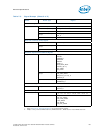
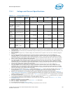
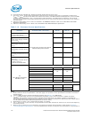
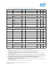
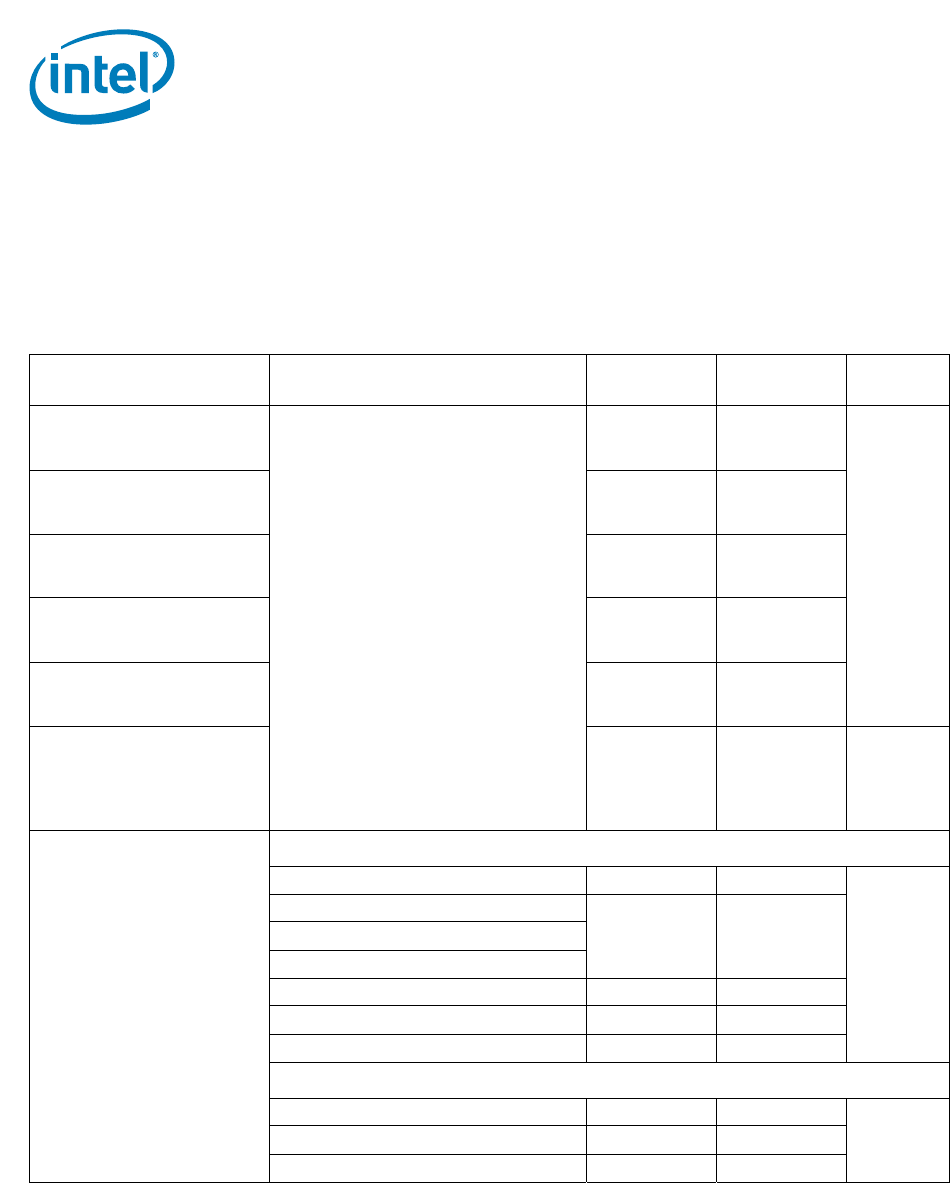
Table 7-12. Processor Current Specifications
Parameter Symbol and
Definition
Processor TDP / Core Count TDC (A) Max (A) Notes
1
I
TT
I/O Termination Supply,
Processor Current on V
TTA
/V
TTD
All Intel® Xeon® processor E5-1600/E5-
2600/E5-4600 product families
20 24 2, 3, 5, 6
I
SA
System Agent Supply, Processor
Current on V
SA
20 24
I
CCD_01
DDR3 Supply, Processor Current
V
CCD_01
34
I
CCD_23
DDR3 Supply, Processor Current
V
CCD_23
34
I
CCPLL
PLL Supply, Processor Current on
V
CCPLL
22
I
CCD_01_S3
I
CCD_23_S3
DDR3 Supply, Processor Current
on V
CCD_01
/V
CCD_23
in System S3 Standby State
-- 1 4
I
CC
Core Supply, Processor
Current on V
CC
8-core/6-core
150 W 8-core 155 185 2, 5, 6
135 W 8-core
135 165130 W 6-core, 6-core 1S WS and 8-core
115 W 8-core
95 W 6-core, 8-core and LV95W-8C 115 135
70 W 8-core and LV70W-8C 80 100
60 W 6-core 70 85
4-core/2-core
130 W 4-core and 4-core 1S WS 115 150 2, 5, 6
95 W 4-core 115 135
80 W 2-core and 4-core 80 100