


Electrical Specifications
172 Intel® Xeon® Processor E5-1600/E5-2600/E5-4600 Product Families
Datasheet Volume One
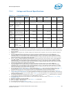
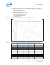
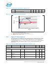
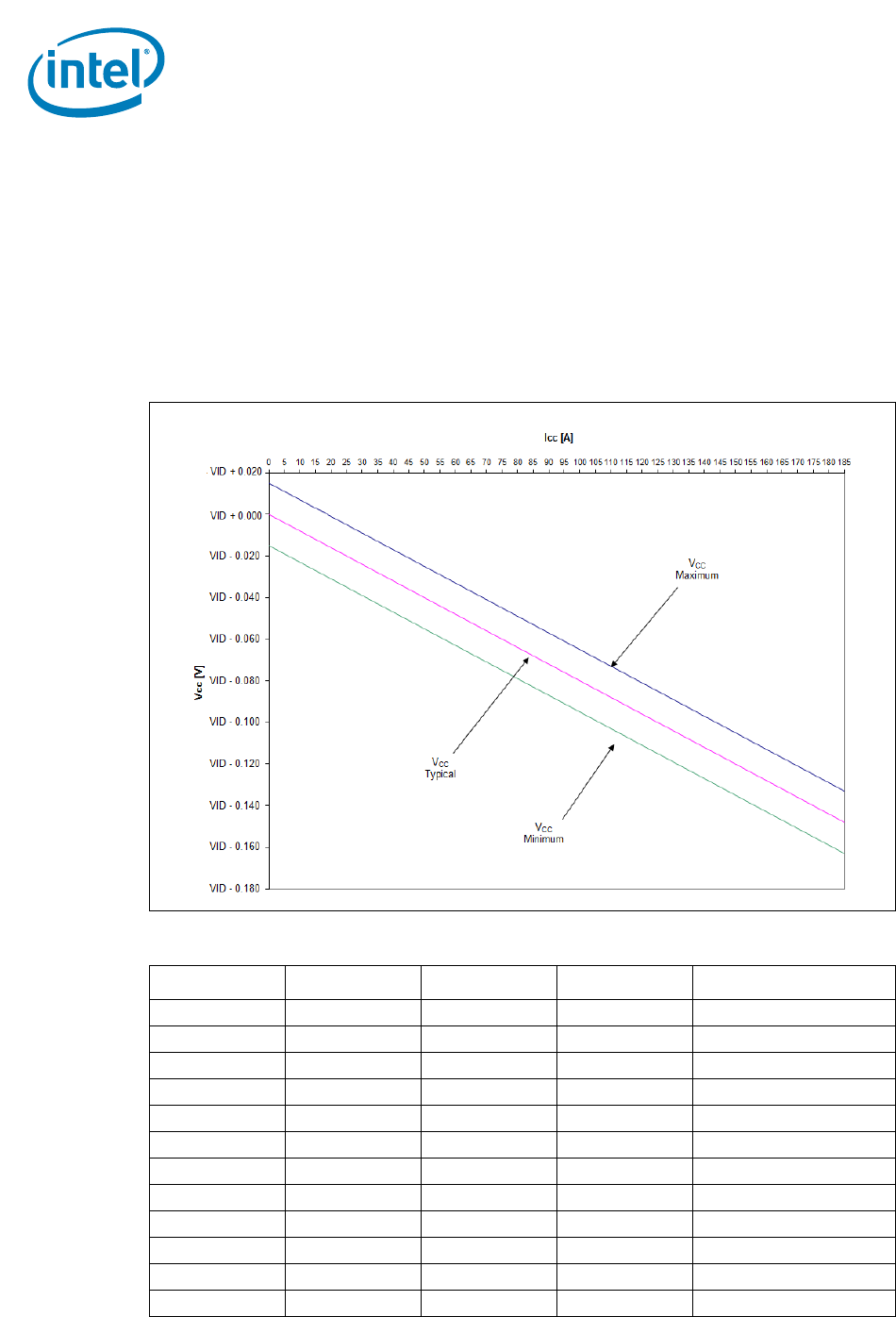
2. This table is intended to aid in reading discrete points on graph in Figure 7-3.
3. The loadlines specify voltage limits at the die measured at the VCC_SENSE and VSS_VCC_SENSE lands.
Voltage regulation feedback for voltage regulator circuits must also be taken from processor VCC_SENSE
and VSS_VCC_SENSE lands. Refer to the
VR12/IMVP7 Pulse Width Modulation Specification for loadline
guidelines and VR implementation details.
4. The Vcc_min and Vcc_max loadlines represent static and transient limits. Please see Section 6 for Vcc
Overshoot specifications.
5. The Adaptive Loadline Positioning slope is 0.8 m
Ω.
6. The 8/6-core Icc ranges are as follows:
• 0-185 A for 150 W processor
• 0-165 A for 135 W, 130 W, 115 W processors
• 0-135 A for 95 W, LV95W-8C processors
• 0-100 A for 70 W, LV70W-8C processors
• 0-85 A for 60 W processors
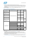
Figure 7-3. 8/6-Core: V
CC
Static and Transient Tolerance Loadlines
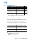
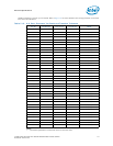
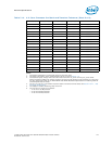
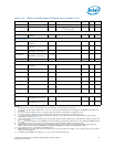
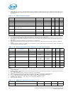
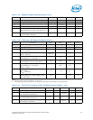
Table 7-14. 4/2-Core: Processor V
CC
Static and Transient Tolerance (Sheet 1 of 2)
I
CC
(A) V
CC_MAX
(V) V
CC_TYP
(V) V
CC_MIN
(V) Notes
0 VID + 0.015 VID - 0.000 VID - 0.015 1,2,3,4,5,6
5 VID + 0.011 VID - 0.004 VID - 0.019 1,2,3,4,5,6
10 VID + 0.007 VID - 0.008 VID - 0.023 1,2,3,4,5,6
15 VID + 0.003 VID - 0.012 VID - 0.027 1,2,3,4,5,6
19 VID + 0.000 VID - 0.015 VID - 0.030 1,2,3,4,5,6
25 VID - 0.005 VID - 0.020 VID - 0.035 1,2,3,4,5,6
30 VID - 0.009 VID - 0.024 VID - 0.039 1,2,3,4,5,6
35 VID - 0.013 VID - 0.028 VID - 0.043 1,2,3,4,5,6
40 VID - 0.017 VID - 0.032 VID - 0.047 1,2,3,4,5,6
45 VID - 0.021 VID - 0.036 VID - 0.051 1,2,3,4,5,6
50 VID - 0.025 VID - 0.040 VID - 0.055 1,2,3,4,5,6
55 VID - 0.029 VID - 0.044 VID - 0.059 1,2,3,4,5,6