Intel® Xeon® Processor E5-1600/E5-2600/E5-4600 Product Families 139
Datasheet Volume One
5.2.2.1 Frequency/SVID Control
The processor uses Frequency/SVID control whereby TCC activation causes the
processor to adjust its operating frequency (via the core ratio multiplier) and VCC input
voltage (via the SVID signals). This combination of reduced frequency and voltage
results in a reduction to the processor power consumption.
This method includes multiple operating points, each consisting of a specific operating
frequency and voltage. The first operating point represents the normal operating
condition for the processor. The remaining points consist of both lower operating
frequencies and voltages. When the TCC is activated, the processor automatically
transitions to the new lower operating frequency. This transition occurs very rapidly (on
the order of microseconds).Once the new operating frequency is engaged, the
processor will transition to the new core operating voltage by issuing a new SVID code
to the VCC voltage regulator. The voltage regulator must support dynamic SVID steps
to support this method. During the voltage change, it will be necessary to transition
through multiple SVID codes to reach the target operating voltage. Each step will be
one SVID table entry (see Table 7-3). The processor continues to execute instructions
during the voltage transition. Operation at the lower voltages reduces the power
consumption of the processor.
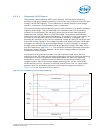
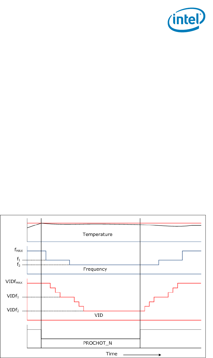
A small amount of hysteresis has been included to prevent rapid active/inactive
transitions of the TCC when the processor temperature is near its maximum operating
temperature. Once the temperature has dropped below the maximum operating
temperature, and the hysteresis timer has expired, the operating frequency and
voltage transition back to the normal system operating point via the intermediate
SVID/frequency points. Transition of the SVID code will occur first, to insure proper
operation once the processor reaches its normal operating frequency. Refer to
Figure 5-33 for an illustration of this ordering.
Figure 5-33. Frequency and Voltage Ordering


