


56 Intel® Xeon® Processor E5-1600/E5-2600/E5-4600 Product Families
Datasheet Volume One
compared to the input PROCHOT_N signal assertion method. Both power limit enabling
and initialization of power limit values can be done in the same command cycle. Setting
a power limit for the VCC plane enables turbo modes for associated logic. External VR
protection is guaranteed during boot through operation at safe voltage and frequency.
All RAPL parameter values including the power limit value, control time window, clamp
mode and enable bit will have to be specified correctly even if the intent is to change
just one parameter value when programming over PECI.
The usefulness of the VCC power plane RAPL may be somewhat limited if the platform
has a fully compliant external voltage regulator. However, platforms using lower cost
voltage regulators may find this feature useful. The VCC RAPL value is generally
expected to be a static value after initialization and there may not be any use cases for
dynamic control of VCC plane power limit values during run time. BIOS may be ideally
used to read the VR (and associated heat sink) capabilities and program the PCU with
the power limit information during boot. No matter what the method is, Intel
recommends exclusive use of just one entity or interface, PECI for instance, to manage
VCC plane power limiting needs. If PECI is being used to manage VCC plane power
limiting activities, BIOS should lock out all subsequent inband VCC plane power limiting
accesses by setting bit 31 of the PP0_POWER_LIMIT MSR and CSR to ‘1’.
The same conversion formula used for DRAM Power Limiting (see Section 2.5.2.6.9)
should be applied for encoding or programming the ‘Control Time Window’ in bits
[23:17].
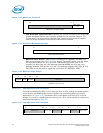
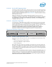
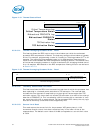
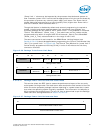
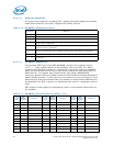
2.5.2.6.26 Package Power Limits For Multiple Turbo Modes
This feature allows the PECI host to program two power limit values to support multiple
turbo modes. The operating systems and drivers can balance the power budget using
these two limits. Two separate PECI requests are available to program the lower and
upper 32 bits of the power limit data shown in Figure 2-36. The units for the Power
Limit and Control Time Window are determined as per the Package Power SKU Unit
settings described in Section 2.5.2.6.13 while the valid range for power limit values are
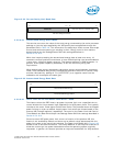
determined by the Package Power SKU settings described in Section 2.5.2.6.14. Setting
the Clamp Mode bits is required to allow the cores to go into power states below what
the operating system originally requested. The Power Limit Enable bits should be set to
enable the power limiting function. Power limit values, enable and clamp mode bits can
all be set in the same command cycle. All RAPL parameter values including the power
limit value, control time window, clamp mode and enable bit will have to be specified
correctly even if the intent is to change just one parameter value when programming
over PECI.
Intel recommends exclusive use of just one entity or interface, PECI for instance, to
manage all processor package power limiting and budgeting needs. If PECI is being
used to manage package power limiting activities, BIOS should lock out all subsequent
inband package power limiting accesses by setting bit 31 of the
PACKAGE_POWER_LIMIT MSR and CSR to ‘1’. The ‘power limit 1’ is intended to limit
processor power consumption to any reasonable value below TDP and defaults to TDP.
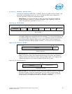
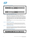
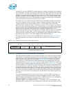
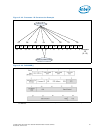
Figure 2-35. Power Limit Data for VCC Power Plane
VCC Power Plane Power Limit Data
Power Limit
Enable
1523
VCC Plane Power Limit
14 0
Clamp
Mode
16
Control Time
Window
1731
RESERVED
24