Intel® Server Board SE7320SP2 & Intel Server Board SE7525GP2 TPS List of Figures
Revision 2.0
12
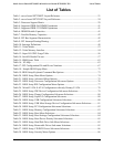
List of Figures
Figure 1 - SE7320SP2 Board Layout ............................................................................................20
Figure 2 - SE7525GP2 Board Layout............................................................................................23
Figure 3 – Server Board SE7320SP2 Block Diagram ...................................................................25
Figure 4 –Server Board SE7525GP2 Block Diagram....................................................................26
Figure 5. CEK Processor Mounting...............................................................................................28
Figure 6 - DIMM Socket Configuration ........................................................................................40
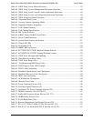
Figure 7 - Interrupt Routing Diagram (Intel 6300ESB Internal) ...................................................49
Figure 8 - Interrupt Routing Diagram............................................................................................50
Figure 9 - Intel® Xeon™ Processor Memory address Space........................................................58
Figure 10 - DOS Compatibility Region.........................................................................................59
Figure 11 - Extended Memory Map...............................................................................................61
Figure 12 - CONFIG_ADDRES Register......................................................................................66
Figure 13 - Block Diagram of Platform Managment Architecture..............................................104
Figure 14: mBMC in a Server Management System...................................................................108
Figure 15: External Interfaces to mBMC.....................................................................................109
Figure 16 - IPMI-over-LAN ........................................................................................................112
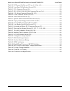
Figure 17: Power Supply Control Signals ...................................................................................119
Figure 18 - Location of Diagnostic LEDs on Server board (Example only) ...............................139
Figure 19. System Configuration Jumpers (J17) .........................................................................162
Figure 20. BIOS Bank Jumper (J26)............................................................................................162
Figure 21. Output Voltage Timing...............................................................................................166
Figure 22. Turn on / off Timing...................................................................................................168


