


Intel® Server Board SE7320SP2 & Intel Server Board SE7525GP2 TPS Connector Definitions and Pin-Outs
Revision 2.0
151
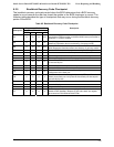
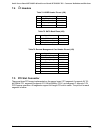
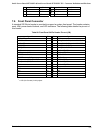
7.4 I
2
C Headers
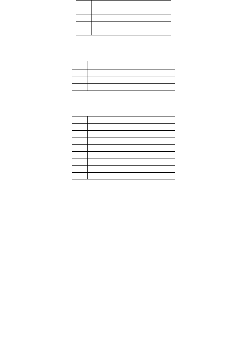
Table 74. HSBP Header Pin-out (J54)
Pin Signal Name Description
1 HR_SMB_P5V_DAT Data Line
2 GND GROUND
3 HR_SMB_P5V_CLK Clock Line
4 GND GROUND
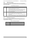
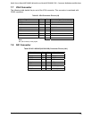
Table 75. SATA Back Plane (J56)
Pin Signal Name Description
1 SATA_EEPROM_SDAT Data Line
2 GND GROUND
3 SATA_EEPROM_SCLK Clock Line
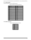
Table 76. Remote Management Card Header Pin-out (J33)
Pin Signal Name Description
1 MBMC_SMB_PHL_DAT Data Line
2 GND GROUND
3 MBMC_SMB_PHL_CLK Clock Line
4 P5V_STBY POWER
5 NC
6 NC
7 NC
8 NC
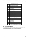
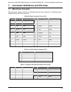
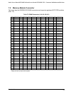
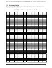
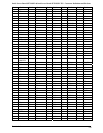
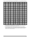
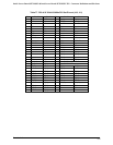
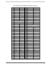
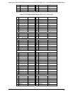
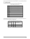
7.5 PCI Slot Connector
There are three PCI buses implemented on the server board. PCI segment A supports 5V 32-
bit/33MHz PCI, segment B supports 3.3V 64-bit/66MHz PCI-X, and segment C supports 3.3V
PCI Express operation. All segments support full-length PCI add-in cards. The pin-out for each
segment is below.