


Intel® Server Board SE7320SP2 & Intel Server Board SE7525GP2 TPS Connector Definitions and Pin-Outs
Revision 2.0
156
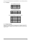
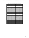
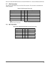
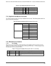
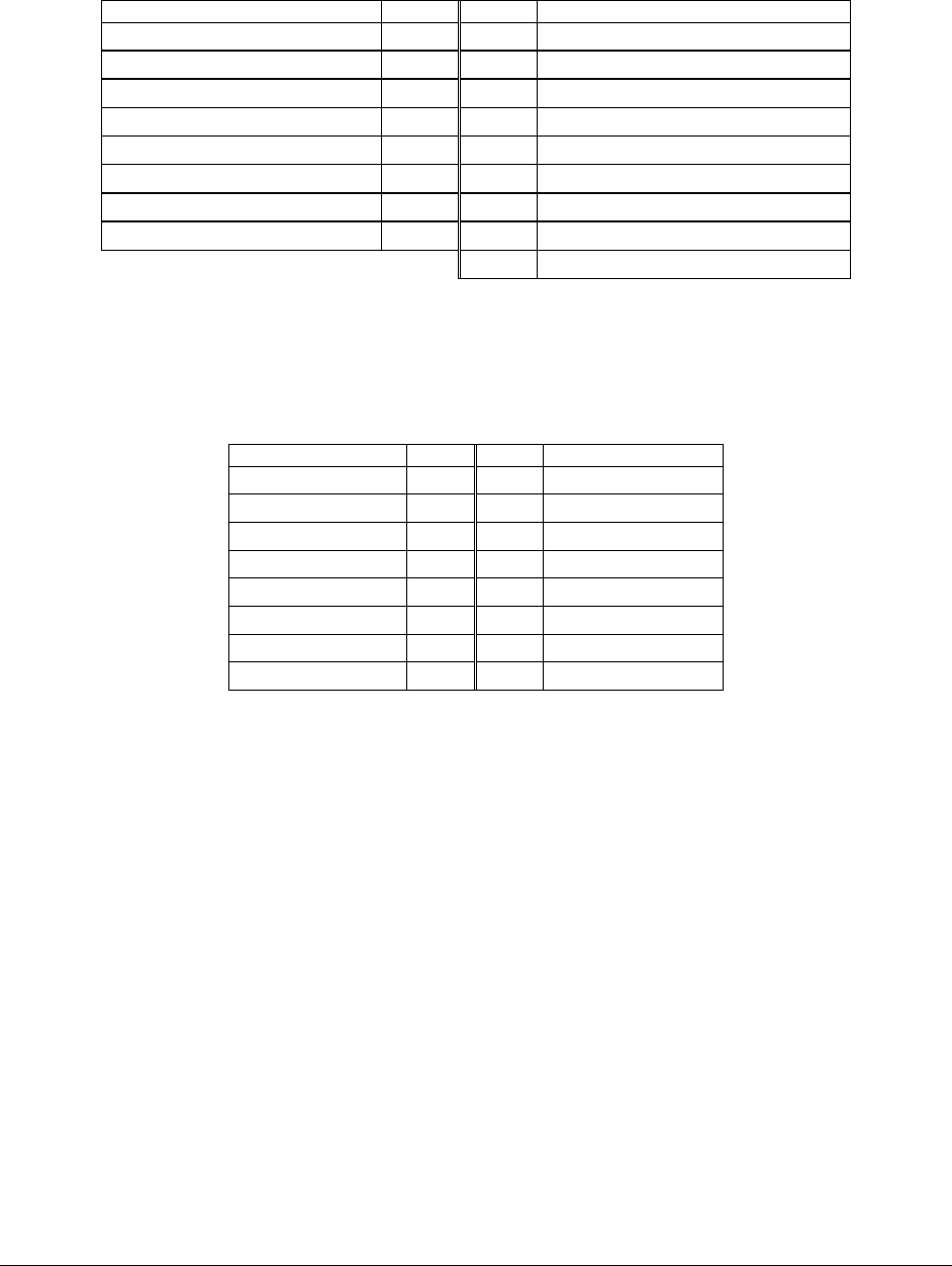
7.7 VGA Connector
The following table details the pin-out of the VGA connector. This connector is combined with
COM1 connector.
Table 81. VGA Connector Pin-out (J4)
Signal Name Pin Pin Signal Name
RED B1 B9 Fused VCC (+5V) (NO SUPPORT)
GREEN B2 B10 NC
BLUE B3 B11 NC
NC B4 B12 DDCDAT
GND B5 B13 HSY
GND B6 B14 VSY
GND B7 B15 DDCCLK
GND B8 B16 NC
B17 NC
Note:
NC (No Connect) in this project
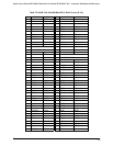
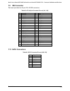
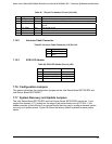
7.8 NIC Connector
Table 82. NIC1-82541GI(10/100/1000) Connector Pin-out (JA1)
Signal Name Pin Pin Signal Name
GND 1 9 MDI_3N
MDI_2N 2 10 MDI_0N
MDI_2P 3 11 MDI_0P
MDI_1P 4 12 GND
MDI_1N 5 13 ACT_L
GND 6 14 LINK_L
GND 7 15 LINK1000_L
MDI_3P 8 16 LINK100_L