


Intel® Server Board SE7320SP2 & Intel Server Board SE7525GP2 TPS Functional Architecture
Revision 2.0
60
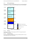
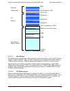
3.7.1.1.3 Video or SMM Memory
The 128 KB Graphics Adapter Memory region at 0A0000h to 0BFFFFh is normally mapped to
the VGA controller on the PCI bus. This region is also the default region for SMM space.
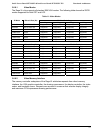
3.7.1.1.4 Add-in Card BIOS and Buffer Area
The 128 KB region between addresses 0C0000h to 0DFFFFh is divided into eight segments of
16 KB segments mapped to ISA memory space, each with programmable attributes, for
expansion cards buffers. Historically, the 32 KB region from 0C0000h to 0C7FFFh has
contained the video BIOS location on the video card.
3.7.1.1.5 Extended System BIOS
This 64 KB region from 0E0000h to 0EFFFFh is divided into 4 blocks of 16 KB each, and may
be mapped with programmable attributes to map to either main memory or to the PCI bus.
Typically this area is used for RAM or ROM. This region can also be used extended SMM space.
3.7.1.1.6 System BIOS
The 64 KB region from 0F0000h to 0FFFFFh is treated as a single block. By default this area is
normally read/write disabled with accesses forwarded to the PCI bus. Through manipulation of
R/W attributes, this region can be shadowed into main memory.
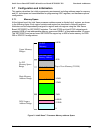
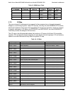
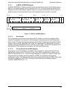
3.7.1.2 Extended Memory
Extended memory is defined as all address space greater than 1MB. Extended Memory region
covers 8GB maximum of address space from addresses 0100000h to FFFFFFFh, as shown in
the following figure. PCI memory space can be remapped to top of memory (TOM).