


Intel® Server Board SE7320SP2 & Intel Server Board SE7525GP2 TPS Functional Architecture
Revision 2.0
27
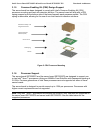
3.1 Processor Sub-system
The support circuitry for the processor sub-system consists of the following:
• Dual 604-pin zero insertion force (ZIF) processor sockets
• Processor host bus AGTL+ support circuitry
• Reset configuration logic
• Processor module presence detection logic
• BSEL detection capabilities
• CPU signal level translation
• Common Enabling Kit (CEK) CPU retention support
3.1.1 Processor VRD
The server board has two Voltage Regulator Devices (VRDs) providing the appropriate voltages
to the installed processors. Each VRD is compliant with the VRD 10.1 specification and is
designed to support Intel
®
Xeon™ processors that require up to a sustained maximum current
of 105 Amps and peak support of 120A.
The server board supports the Flexible Mother Board (FMB) specification for all 800MHz FSB
Intel Xeon processors with respect to current requirements and processor speed requirements.
FMB is an estimation of the maximum values the 800MHz FSB versions of the Intel Xeon
processors will have over their lifetime. The value is only an estimate and actual specifications
for future processors may differ. At present, the current demand per FMB is a sustained
maximum of a 105 Amps and peak support of 120 Amps.
3.1.2 Reset Configuration Logic
The BIOS determines the processor stepping, cache size, etc through the CPUID instruction. All
processors in the system must operate at the same frequency; have the same cache sizes and
same VID. No mixing of product families is supported. Processors run at a fixed speed and
cannot be programmed to operate at a lower or higher speed.
3.1.3 Processor Module Presence Detection
Logic is provided on the server board to detect the presence and identity of installed processors.
In dual processor configurations, the on-board mini Baseboard Management Controller (mBMC)
must read the processor voltage identification (VID) bits for each processor before turning on
the VRD. If the VIDs of the two processors are not identical, then the mBMC will not turn on the
VRD. Prior to enabling the embedded VRD, circuitry on the server board ensures that the
following criteria are met:
• In a uni-processor configuration, CPU 1 is installed.
• Only supported processors are installed in the system to prevent damage to the MCH.
• In dual processor configurations, both processors support the same FSB frequency.
3.1.4 GTL2006
The GTL2006 is a 13-bit translator designed for 3.3V to GTL/GTL+ translations to the system
bus. The translator incorporates all the level shifting and logic functions required to interface
between the processor subsystem and the rest of the system.