


Intel® Server Board SE7320SP2 & Intel Server Board SE7525GP2 TPS Platform Management
Revision 2.0
123
5.3.4.4 Chassis ID Button and LED
The front panel interface supports a Chassis Identify Button and a corresponding Blue Chassis
Identify LED. A second Blue Chassis Identify LED is mounted on the back edge of the server
board where it may be visible when viewed from the back of an integrated system.
The LED can provide a mechanism for identifying one system out of a group of identical
systems in a high density rack environment
The Chassis Identify LED can be turned on either locally via the push-button signal, or by local
or remote software using the IPMI Chassis Identify command. The following list summarizes the
Chassis Identify Push-button and LED operation:
• The Identify signal state is preserved on Standby power across system power-on/off and
system hard resets. It is not preserved if A/C power is removed. The initial LED state is
Off when A/C power is applied.
• The IPMI Chassis Identify command can also be used to control the LED. If a the
Chassis Identify command is used to turn the LED On, the command will automatically
time out and turn off the LED unless another Chassis Identify command to turn on the
LED is received. The default timeout for the command is 15 seconds. The server board
supports the optional command parameter to allow the timeout to be set anywhere from
1 to 255 seconds.
• The optional timeout parameter in the Chassis Identify command also allows software to
tell the LED to go Off immediately.
• The Chassis Identify Pushbutton works using a “push-on/push-off” operation. Each press
of the push-button toggles the LED signal state between On and Off. If the pushbutton is
used to turn the LED On, it will stay on indefinitely, until either the button is pressed
again or a Chassis Identify or Chassis Identify LED command causes the LED to go Off.
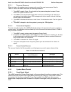
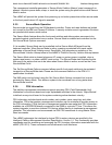
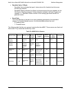
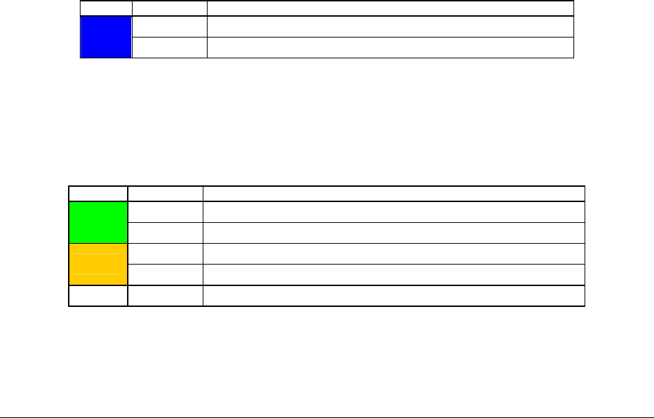
Table 53: Chassis ID LEDs
Color Condition When
Off Ok
Blue
Blink Identify button pressed or Chassis Identify command executed
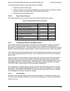
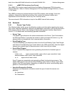
5.3.4.5 Status/Fault LED
The following table shows mapping of sensors/faults to the LED state.
Table 54: Fault/Status LED
Color Condition When
Solid System Ready
Green
Blink System Ready, but degraded. CPU fault, DIMM killed
Solid Critical Failure: critical fan, voltage, temperature state
Amber
Blink Non-Critical Failure: non-critical fan, voltage, temperature state
Off Solid Not Ready. POST error/NMI event/CPU or terminator missing