


Intel® Server Board SE7320SP2 & Intel Server Board SE7525GP2 TPS Connector Definitions and Pin-Outs
Revision 2.0
159
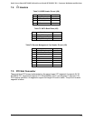
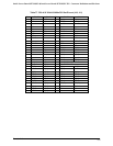
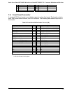
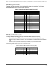
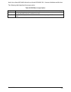
7.12 Floppy Connector
The board provides a standard 34-pin interface to the floppy drive controller. The following
tables detail the pin-out of the 34-pin floppy connector.
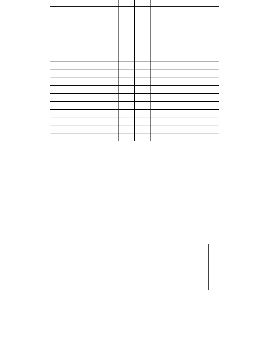
Table 87. Legacy 34-pin Floppy Connector Pin-out (J47)
Signal Name Pin Pin Signal Name
GND 1 2 FDDENSEL
GND 3 4 Unused
KEY 5 6 FDDRATE0
GND 7 8 FDINDEX#
GND 9 10 FDMTR0#
GND 11 12 FDR1#
GND 13 14 FDR0#
GND 15 16 FDMTR1#
Unused 17 18 FDDIR
GND 19 20 FDSTEP#
GND 21 22 FDWDATA#
GND 23 24 FDWGATE#
GND 25 26 FDTRK0#
Unused 27 28 FLWP#
GND 29 30 FRDATA#
GND 31 32 FHDSEL#
GND 33 34 FDSKCHG#
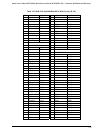
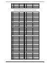
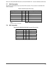
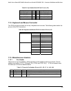
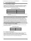
7.13 Serial Port Connector
Two serial ports are provided on the SE7320SP2 and server board SE7525GP2s.
• A standard, external DB9 serial connector is located on the back edge of the server
board to supply a Serial A interface. And this connector is combined with VGA connector
(J4)
• A Serial B port is provided through a 9-pin header (J15) on the server board.
The following tables detail the pin-outs of these two ports.
Table 88. External DB9 Serial A Port Pin-out (J8A1)
Signal Name Pin Pin Signal Name
SERIAL_DCD1_FB T1 T6 SERIAL_DSR1_FB
SERIAL_RX1_FB T2 T7 SERIAL_RTS1_FB
SERIAL_TX1_FB T3 T8 SERIAL_CTS1_FB
SERIAL_DTR1_FB T4 T9 SERIAL_RING1_FB
GND T5