


Intel® Server Board SE7320SP2 & Intel Server Board SE7525GP2 TPS Connector Definitions and Pin-Outs
Revision 2.0
162
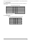
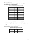
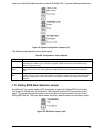
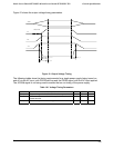
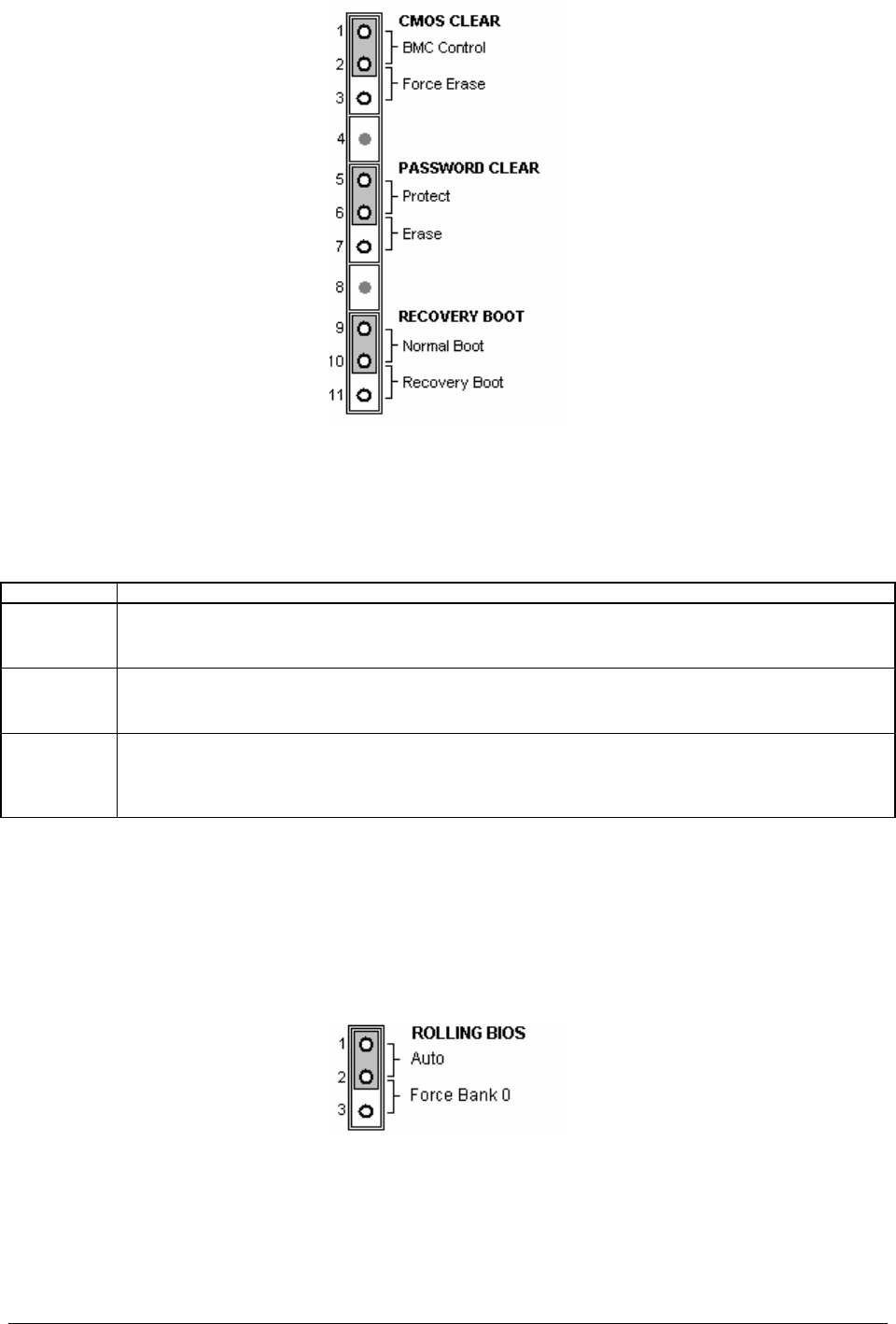
Figure 19. System Configuration Jumpers (J17)
The following table describes each jumper option.
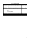
Table 95. Configuration Jumper Options
Option Description
CMOS Clear If pins 1 and 2 are jumpered (default), preservation of configuration CMOS through system reset is
controlled by the mBMC. If pins 2 and 3 are jumpered, CMOS contents are set to manufacturing
default during system reset.
Password
Clear
If pins 1 and 2 are jumpered (default), the current BIOS Setup Utility passwords are maintained during
system reset. If pins 2 and 3 are jumpered, the Administrator and user passwords are cleared on
reset.
Recovery
Boot
If pins 1 and 2 are jumpered (default) the system will attempt to boot using the BIOS programmed in
the Flash memory. If pins 2 and 3 are jumpered, the BIOS will attempt a recovery boot, loading BIOS
code from a floppy disk into the Flash device. This is typically used when the BIOS code has been
corrupted.
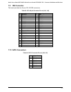
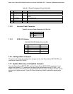
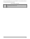
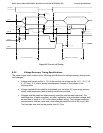
7.18 Rolling BIOS Bank Selection Jumper
An additional 3-pin jumper header (J26) is provided to support the Rolling BIOS functionality.
This jumper is located near the processor 2 VRD heatsink and the SATA connectors on the
board. The jumper provides the option to force the board to boot from Bank 0 as part of the
Rolling BIOS feature. The figure below shows the factory default location for the jumper option.
Figure 20. BIOS Bank Jumper (J26)