


Intel® Server Board SE7320SP2 & Intel Server Board SE7525GP2 TPS Connector Definitions and Pin-Outs
Revision 2.0
161
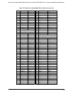
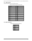
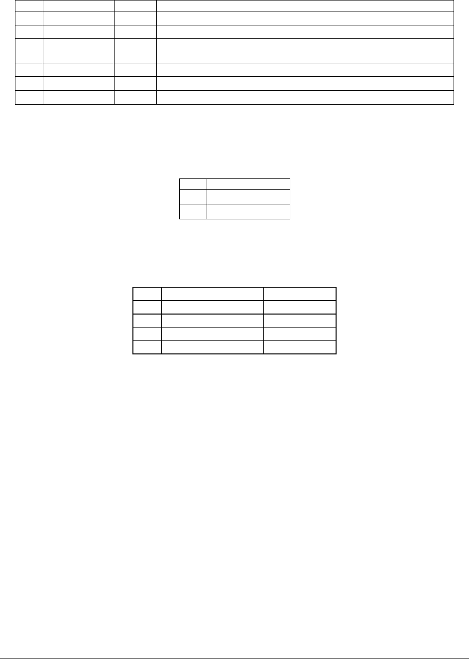
Table 92 . Six-pin Fan headers Pin-out (J44, J46)
Pin Signal Name Type Description
1 Ground Power GROUND is the power supply ground
2 Fan Power Power Fan Power
3 Fan Tach Out FAN_TACH signal is connected to the Super IO to monitor the FAN
speed.
4 Fan PWM Out Fan speed control
5 N/C
6 N/C
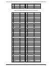
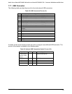
7.15.2 Intrusion Cable Connector
Table 93. Intrusion Cable Connector (J19) Pin-Out
Pin Signal Name
1 INTRUDER_N
2 GND
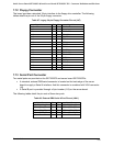
7.15.3 SCSI LED Header
Table 94. SCSI LED Header Pin-out (J26)
Pin Signal Name Description
1 GND Ground
2 SCSI_CONN_LED_N Activity Signal
3 SCSI_CONN_LED_N Activity Signal
4 GND Ground
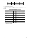
7.16 Configuration Jumpers
This section describes the configuration jumpers on the Intel Server Board SE7320SP2 and
Intel Server Board SE5725GP2.
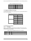
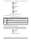
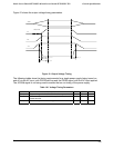
7.17 System Recovery and Update Jumpers
The Intel Server Board SE7320SP2 and Intel Server Board SE7525GP2 provide an 11-pin
single inline header (J17), located on the edge of the server board next to PCI Slot 1, this
header provides a total of three 3-pin jumper blocks that are used to configure several system
recovery and update options. Figure 19 shows the factory default locations for each jumper
option.