


Intel® Server Board SE7320SP2 & Intel Server Board SE7525GP2 TPS Connector Definitions and Pin-Outs
Revision 2.0
160
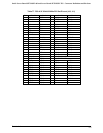
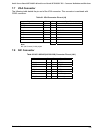
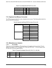
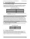
Table 89. 9-pin Header Serial B Port Pin-out (J15)
Signal Name Pin Pin Signal Name
SERIAL_DCD2_FB 1 2 SERIAL_DSR2_FB
SERIAL_RX2_FB 3 4 SERIAL_RTS2_FB
SERIAL_TX2_FB 5 6 SERIAL_CTS2_FB
SERIAL_DTR2_FB 7 8 SERIAL_RING2_FB
GND 9 10 Key
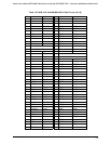
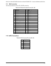
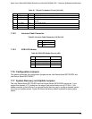
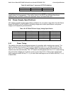
7.14 Keyboard and Mouse Connector
Two PS/2 ports are provided for use by a keyboard and a mouse. The following table details the
pin-out of the PS/2 connectors.
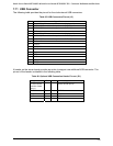
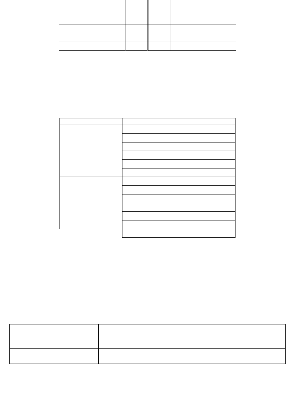
Table 90. Keyboard and Mouse PS/2 Connectors Pin-out (J2)
PS/2 Connectors Pin Signal Name
1 KBDATA
2 NC
3 GND
4 KMPWR
5 KBCLK
Keyboard
6 NC
7 MSEDATA
8 NC
9 GND
10 KMPWR
11 MSECLK
Mouse
12
13,14,15,16,17 GND
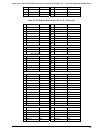
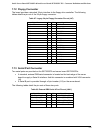
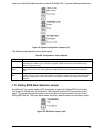
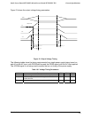
7.15 Miscellaneous Headers
7.15.1 Fan Header
There are six 3-pin fan headers. All fan headers provide speed monitoring on board. The fan
headers are labeled, CPU_1 FAN and CPU_2 FAN, and SYS FAN_1 - 4. All fan headers have
the same pin-out and are detailed below.
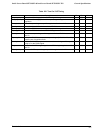
Table 91. Three-pin Fan Headers Pin-out (J51, J52, J7, J1, J45, J48)
Pin Signal Name Type Description
1 Ground Power GROUND is the power supply ground
2 Fan Power Power Fan Power
3 Fan Tach Out FAN_TACH signal is connected to the Super IO to monitor the FAN
speed.