


Intel® Server Board SE7320SP2 & Intel Server Board SE7525GP2 TPS Connector Definitions and Pin-Outs
Revision 2.0
158
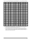
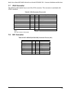
7.11 USB Connector
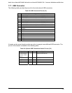
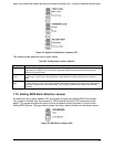
The following table provides the pin-out for the dual external USB connectors.
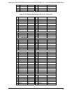
Table 85. USB Connectors Pin-out (J3)
Pin Signal Name
1 Fused VCC (+5V /w over current monitor of both port 3)
2 DATAN3 (Differential data line paired with DATAH3)
3 DATAP3 (Differential data line paired with DATAL3)
4 GND
5 Fused VCC (+5V /w over current monitor of both port 2)
6 DATAN2 (Differential data line paired with DATAH2)
7 DATAP2 (Differential data line paired with DATAL2)
8 GND
9 CTS_N
10 DSR_DCD
11 SIN
12 RI_N
13 GND
14 SIUT
15 DTR_N
16 RTS_N
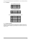
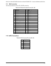
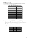
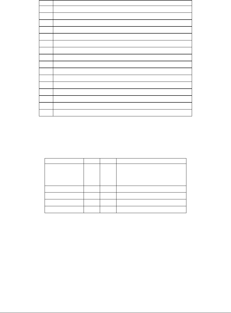
A header on the server board provides an option to support one additional USB connector. The
pin-out of the header is detailed in the following table.
Table 86. Optional USB Connection Header Pin-out (J31)
Signal Name Pin Pin Signal Name
Fused VCC (+5V
/w over current
monitor of both
port 1)
1 2 Fused VCC (+5V /w over current
monitor of both port 0)
DATAN1 3 4 DATAN0
DATAP1 5 6 DATAP0
GND 7 8 GND
Key 9 10 NC