Hardware Installation
3-28 Issue 5 June 1999
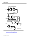
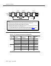
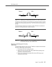
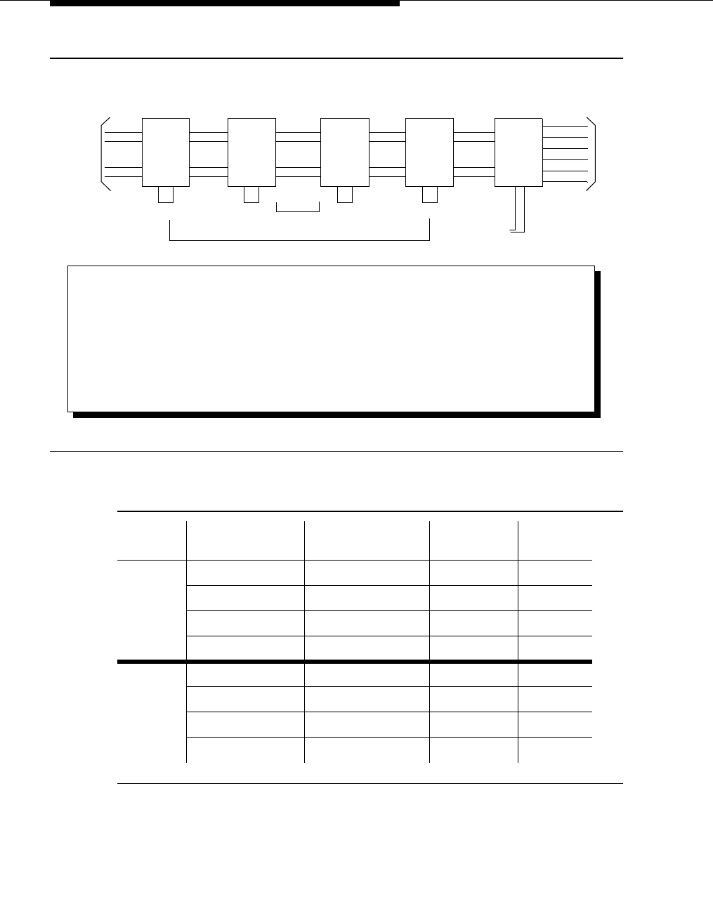
Figure 3-11. DWBS Lightning Protection for IROB WFB.
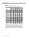
Table 3-4. RC Terminal Assignments for an IROB WFB
WFB Function Backplane
50-Pin
Connector
Modular
Jack
Transmit Tip 104 (UTIPA) 28 3
A Transmit Ring 004 (UTRNGA) 03 6
Receive Tip 103 (URTIPA) 27 1
Receive Ring 003 (URRNGA) 02 2
Transmit Tip 107 (UTTIPB) 31 3
B Transmit Ring 007 (URRNGB) 06 6
Receive Tip 106 (URTIPB) 30 1
Receive Ring 006 (URRNGB) 05 2
To
RC/Cross-
Connect
(see
RXT 1
RXT 2
TXT 3
TXR 6
146E
(see Note 1)
Primary
Protection
Primary
Protection
1151A1 or
1151A2
(see Note 1) (see Note 1) (see Note 1)
WFB
1 RXT 1
2 RXT 2
3 TXT 3
6 TXR 6
7 -48 7
8 GND 8
8 RXT
7 RXR
6 TXT
3 TXR
RXT
RXR
TXT
TXR
RXT 8
RXR 7
TXT 6
TXR 3
1 RXT 1
2 RXR 2
3 TXT 3
6 TXR 6
Note 5)
Out-of-
Building Span
(see Notes 4 and 8)
(see Note 3) (see Note 3)
146E
Line
Protector 1
(see Note 2)
Line
Phone
Equipment
Protector 1
(see Note 2)
117VAC
NOTES:
1. Both primary protectors and the 146E secondary protector must be connected to building ground in accordance
with local and state fire/building codes. In no case should a wire smaller than 14 AWG be used.
2. Use Protector-1 of the 146E secondary protector. Protector-2 cannot be used.
3. Choice of primary protector is determined by local safety codes and procedures.
4. 146E must be used on both ends of the line; otherwise, an incorrect line reversal will make the link uncooperative.
5. The TN789 RC terminal assignments are provided in Table 3-4.
6. TXT and TXR should be assigned as a pair; likewise, RXT and RXR should be assigned as a pair.
7. 1151A1 (without battery backup) and 1151A2 (with battery backup) must be in the same building as the WFB.
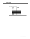
8. Ordering information for the 48V power supply and the secondary protector is provided in Table 3-5.


