Figures
Issue 5 June 1999 vii
2 Switch Administration
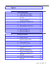
2-1. Optional Features Form (Page 1) 2-2
2-2. Optional Features Form (Page 2) 2-3
2-3. Wireless-Related System Parameters
Form (G3r) 2-4
2-4. Wireless-Related System Parameters
Form (G3si/vs/Prologix
™
)2-5
2-5. Wireless Carrier Frequencies Form 2-8
2-6. Circuit Packs Form 2-9
2-7. System Configuration Form 2-10
2-8. Radio Controller Circuit Pack Form 2-11
2-9. Alias Station Form 2-13
2-10. Station Form (Page 1 of 3) 2-14
2-11. Station Form (Page 2 of 3) 2-17
2-12. Station Form (Page 3 of 3) 2-19
3 Hardware Installation
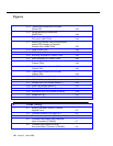
3-1. DWBS Installation Layout 3-8
3-2. Wireless Fixed Base 3-13
3-3. Typical Terminations
and Cross-Connects for WFBs 3-15
3-4. 103 Connecting Block 3-16
3-5. Cross-Connects for WFBs 3-17
3-6. Mounting Points of the WFB 3-19
3-7. Removing the WFB Cover 3-20
3-8. Communication and Power WFB
Connection 3-21
3-9. Internal Fixed-Length Coaxial
Connections From WFB to CAUs 3-22
3-10. Representative Wiring for the
Category 3 4-Pair Twisted Interface 3-24
3-11. DWBS Lightning Protection for
IROB WFB. 3-28
3-12. Mounting Tabs and Slots on the CAU 3-32
3-13. Inserting the Antenna for the 559D
Dipole CAU 3-33


