


2Unpacking to Installation
Installation
2-9
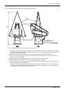
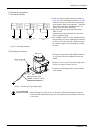
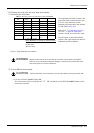
2.2.4 Grounding procedures
(1) Grounding methods
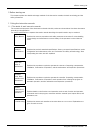
1) There are three grounding methods as shown in
Fig. 2-4, but the dedicated grounding (Fig. 2-4 (a))
should be used for the robot arm and controller
when possible. (Refer to the separate " Controller
Setup, Basic Operation and Maintenance" for
details on the controller grounding.)
2) Use Class D grounding (grounding resistance
100Ω or less).
Dedicated grounding separated from the other
devices should be used.
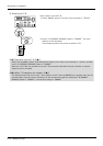
3) Use a AWG#11(3.5mm
2
) or more stranded wire for
the grounding wire. The grounding point should be
as close to the robot arm and controller as possi
-
ble, and the length of the grounding wire should
be short.
Fig.2-4 : Grounding methods
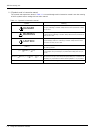
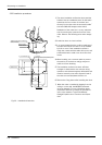
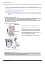
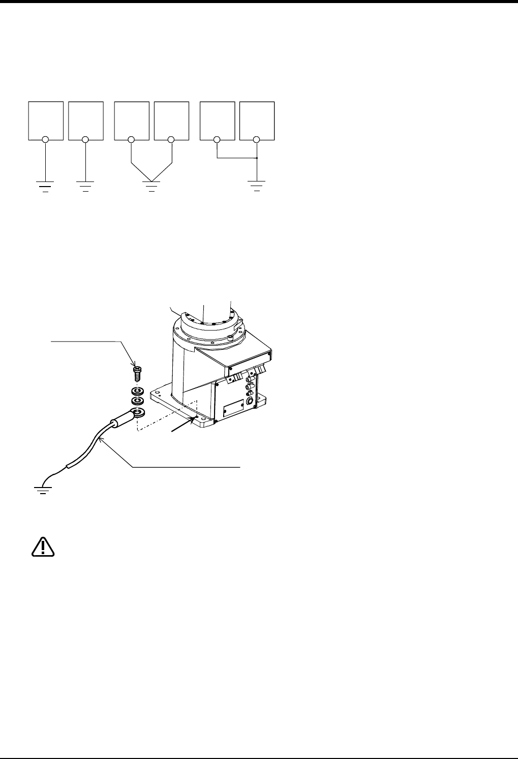
(2) Grounding procedures
1) Prepare the grounding cable (AWG#11(3.5mm
2
)
or more) and robot side installation screw and
washer.
2) If there is rust or paint on the grounding screw
section (A), remove it with a file, etc.
3) Connect the grounding cable to the grounding
screw section.
Fig.2-5 : Connecting the grounding cable
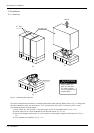
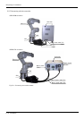
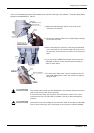
When installing the robot, be sure to allocate a sufficient maintenance space for
connecting the cables between devices and replacing a backup battery at the rear
of the robot.
Robot arm
Controller
and
personal
computer
(a) Dedicated grounding
(Optimum)
(b) Common grounding
(Good)
(c) Common grounding
(Normal)
Robot arm
Controller
and
personal
computer
Robot arm
Controller
and
personal
computer
M4×10, SW, PW
Robot arm
A
Robot grounding cable
(AWG#11 (3.5mm
2
) or more)
(Prepared by customer)
CAUTION