


2-26
Confirming the operation
2Unpacking to Installation
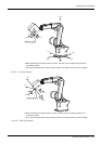
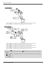
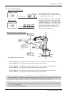
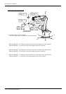
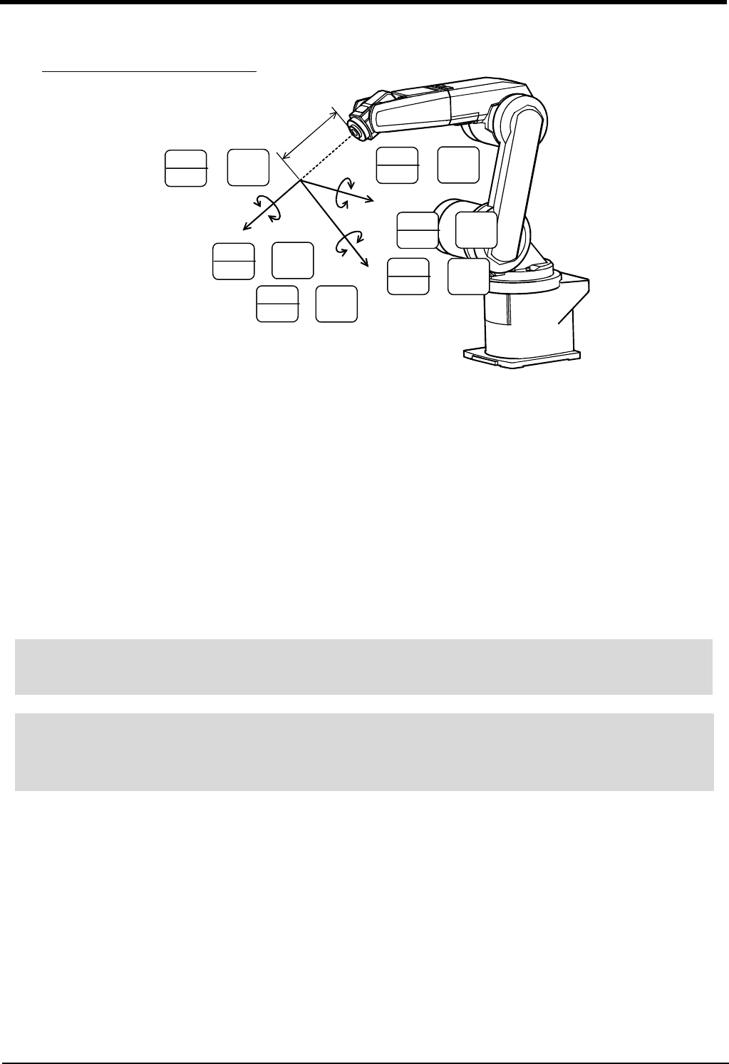
・ When the [MOVE] + [+A (J4)] keys are pressed, The X axis will rotate in the plus direction of the tool
coordinate system.
When the [MOVE] + [-A (J4)] keys are pressed, Rotate in the minus direction.
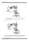
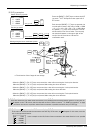
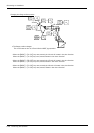
・ When the [MOVE] + [+B (J5)] keys are pressed, The Y axis will rotate in the plus direction of the tool
coordinate system.
When the [MOVE] + [-B (J5)] keys are pressed, Rotate in the minus direction.
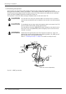
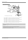
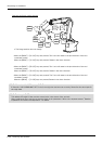
・ When the [MOVE] + [+C (J6)] keys are pressed, The Z axis will rotate in the plus direction of the tool
coordinate system.
When the [MOVE] + [-C (J6)] keys are pressed, Rotate in the minus direction.
STEP
MOVE
+
5
STU
+ C
(J6)
0
ABC
- C
(J6)
STEP
MOVE
+
7
YZ_
+ A
(J4)
STEP
MOVE
+
-
+
-
+
-
+
+X
+Z
T
o
o
l
l
e
n
g
t
h
+Y
2
GHI
- A
(J4)
STEP
MOVE
+
6
VWX
+ B
(J5)
STEP
MOVE
+
1
DEF
- B
(J5)
STEP
MOVE
+
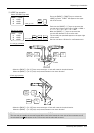
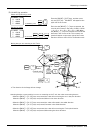
Changing the flange surface posture
* The flange position does not change.
◇◆◇ When alarm No. 5150 occurs ◇◆◇
If alarm No. 5150 (ORIGIN NOT SET) occurs, the origin has not been set correctly. Reconfirm the value input for
the origin data.
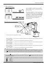
◇◆◇ Tool length ◇◆◇
The default tool length is 0mm, and the control point is the center of the end axis.
After installing the hand, set the correct tool length in the parameters. Refer to the separate manual "Detailed
Explanation of Functions and Operations" for details.