2-22
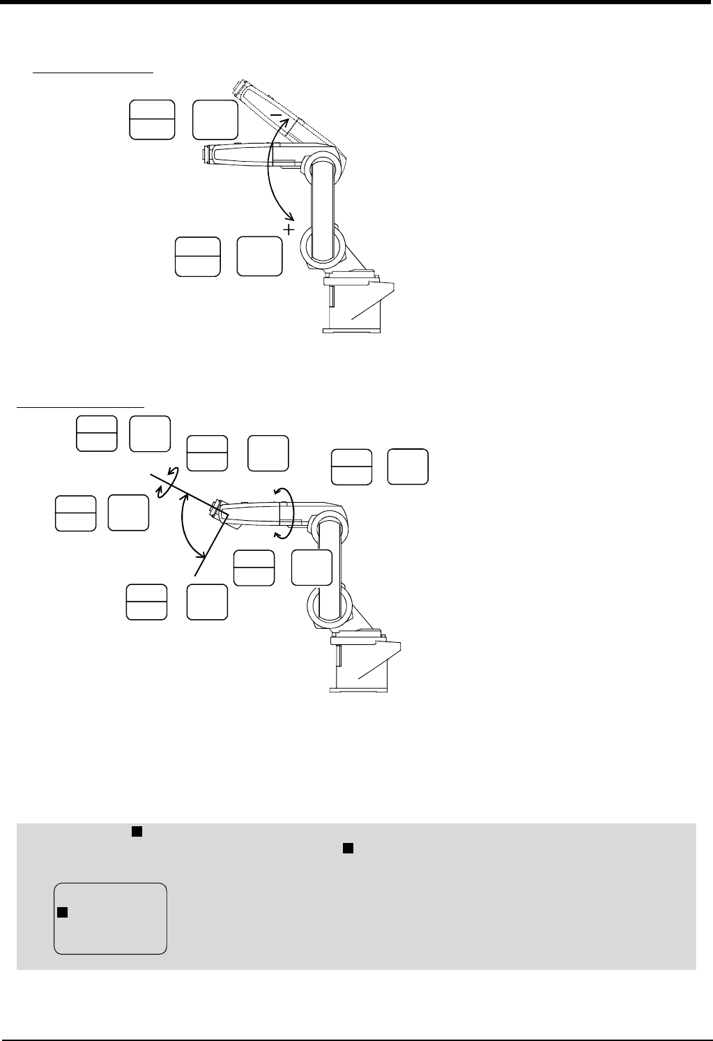
Confirming the operation
2Unpacking to Installation
・ When the [MOVE] + [+Z (J3)] keys are pressed, the J3 axis will rotate in the plus direction.
When the [MOVE] + [-Z (J3)] keys are pressed, Rotate in the minus direction.
・ When the [MOVE] + [+A (J4)] keys are pressed, the J4 axis will rotate in the plus direction.
When the [MOVE] + [-A (J4)] keys are pressed, Rotate in the minus direction.
・ When the [MOVE] + [+B (J5)] keys are pressed, the J5 axis will rotate in the plus direction
When the [MOVE] + [-B (J5)] keys are pressed, Rotate in the minus direction.
・ When the [MOVE] + [+C (J6)] keys are pressed, the J6 axis will rotate in the plus direction
When the [MOVE] + [-C (J6)] keys are pressed, Rotate in the minus direction.
STEP
MOVE
+
3
JKL
- Z
(J3)
STEP
MOVE
+
8
, @\
+ Z
(J3)
J3 axis
J3 axis jog operation
STEP
MOVE
+
6
VWX
+ B
(J5)
STEP
MOVE
+
0
ABC
- C
(J6)
5
STU
+ C
(J6)
STEP
MOVE
+
1
DEF
- B
(J5)
STEP
MOVE
+
7
YZ_
+ A
(J4)
STEP
MOVE
+
J6 axis
J5 axis
J4 axis
+
-
-
+
+
-
2
GHI
- A
(J4)
STEP
MOVE
+
J4, J5 and J6 axis jog
◇◆◇ When an X appears on the T/B screen display ◇◆◇
If the robot is moved outside the movement area, an X will appear. In this case, move the axis in the opposite
direction.
In the example on the left, the J1 axis is at the limit of the plus side movement area.
X
X
JOINT LOW
X J1 +160.00
J2 +20.00
J3 +80.00
X


