


4. Supplemental note for the installation surface receiving force
Supplemental details
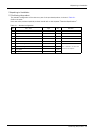
Magnitude of each reaction force added to P2-8 “2.2.3 Installation procedures”.
Table 2-2 shows the maximum reaction force (design values) that may be applied to an installation stand. Please
use these values as reference when designing the installation stand.
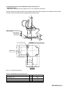
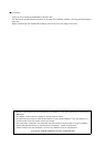
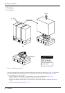
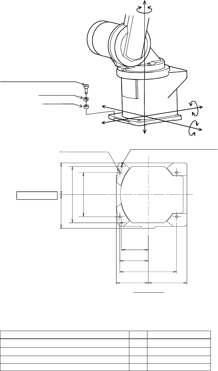
Fig.2-3:Installation dimensions
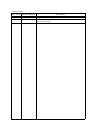
Table 2-2:Magnitude of each reaction force
Item Unit Value
Tilt moment : M
L
N・m
892
Torsional moment : M
T
N・m
892
Horizontal direction translation force : F
H
N 800
Vertical direction translation force : F
V
N 1,400
BFP-A8323-A01-A
115
96
122
204
160
102.5
205
115 140
2-φ6 holes
(prepared holes for φ8 positioning pins)
4-φ9 installation hole
Robot front
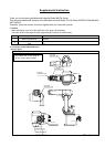
6.3a (Installation)
Base bottom
6.3a (Installation)
4-M8×40 hexagon socket bolt
(Four positions)
Spring washer
Plain washer
F
V
F
H
F
H
F
H
F
H
M
L
M
L
F
V
M
T