


3Installing the option devices
Installing the solenoid valve set (1S-VD01-02/VD02-02/VD03-02/VD04-02)
3-33
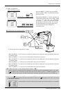
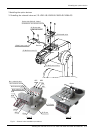
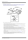
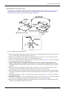
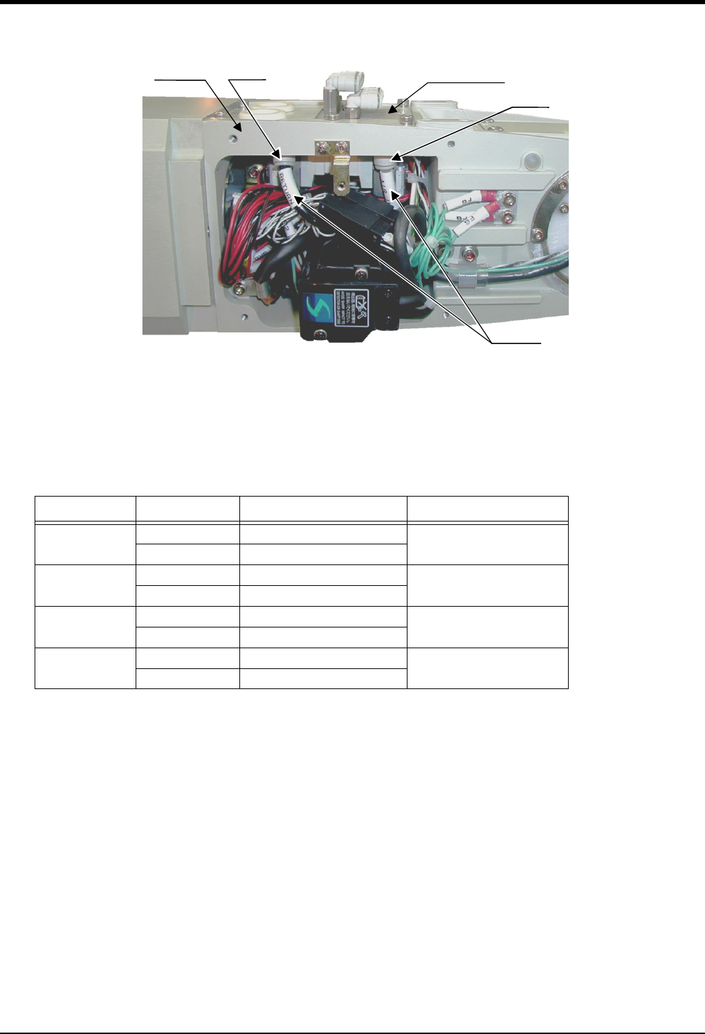
Fig.3-3 : Solenoid valve installation diagram details 2
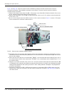
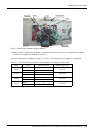
8) When you have completed the installation, reinstall the No.2 arm cover B <2> to its original position, and be
careful not to entangle the cables when you do so.
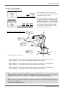
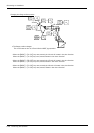
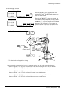
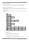
The connections after the installation appear as in Table 3-1 for single type valves, hand 2 is not applicable.
Table 3-1 : Solenoid valve ports and hoses: Correspondence of couplings and hand ports
Hand Hand port Solenoid valve port Solenoid valve used
Hand 1
OPEN A
First set
CLOSE B
Hand 2
OPEN A
Second set
CLOSE B
Hand 3
OPEN A
Third set
CLOSE B
Hand 4
OPEN A
Fourth set
CLOSE B
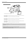
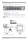
No.2 arm
Air hose
R port
P port
Solenoid valve