


5Maintenance and Inspection
Maintenance and inspection procedures
5-45
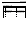
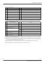
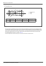
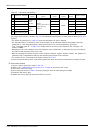
Table 5-3 : Cover names
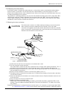
Table 5-4 : Cover installation screw list
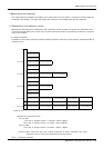
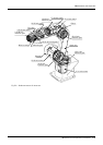
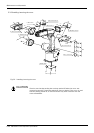
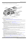
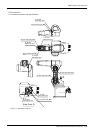
(1) Refer to Fig. 5-3 and remove the cover.
(2) The names of the covers are given in Table 5-3, and a list of the cover installation screws is given in Table 5-4.
(3) There are some covers that may be difficult to remove due to the robot posture. In this case, change the robot
posture with jog operation, and then remove the cover.
(4) When attaching the cover after maintenance and inspection, use the detaching procedure in reverse.
The part Nos. and symbols in Table 5-3 and Table 5-4 correspond to Fig. 5-3.
No. Cover names Qty. Remarks
1 Bottom plate 1
2 Shoulder cover B 1
3 No. 1 arm cover 1
4 Shoulder cover 2
5 Elbow cover A 1
6 No. 2 arm cover C 1
7 No. 2 arm cover A 1
8 No. 2 arm cover B 1
9 Wrist cover 1
No. Installation screw name
Q'ty
Remarks
a Socket bolt M4 × 8 8
b Socket bolt M4 × 10 10
c Socket bolt M4 × 30 4
d Socket bolt M4 × 55 8
e Truss screw M4 × 8 8 RV-6S
10 RV-6SL
f Truss screw M4 × 8 4
g Truss screw M4 × 8 5
h Truss screw M3 × 10 2
i Flat head screw M4 × 8 4