3-36
.Changing the operating range
3Installing the option devices
3.4 .Changing the operating range
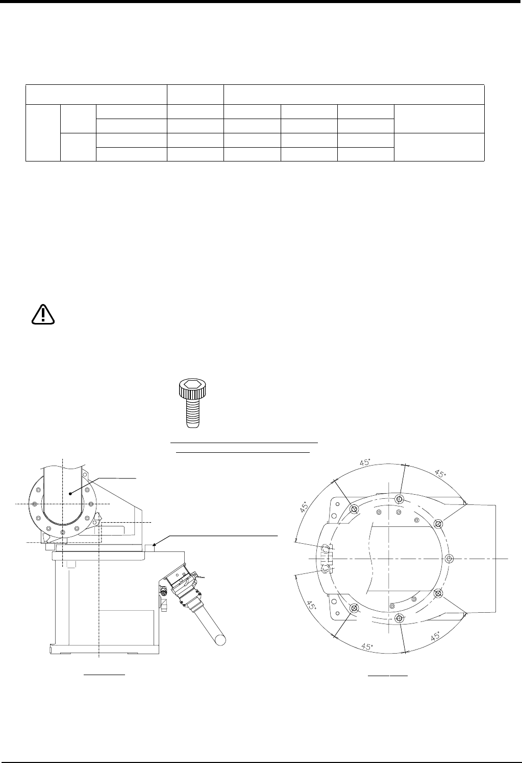
The operating range of the J1 axis can be changed to the range shown in Table 3-2. (Option)
Table 3-2 : Operating range alternative range
Note) The insertion position given in the table indicates the insertion position for the operating range change
stopper. (Refer to
Fig. 3-6.)
The operating range is changed with robot arm settings and parameter settings.
(1) Setting the robot arm
1) Move the upper arm to the posture as shown in Fig. 3-6 by jog operation.
2) Turn OFF the controller power.
3) By referring to Table 3-2 and Fig. 3-6, insert the two stoppers (M10 x 20) used to change the movement
range of J1 axis at the angular position to be changed, and fix securely by applying a clamping torque of 70
N・m to 86 N・m.
Do not remove the stopper for the standard specification of ± 170 degree shown in
Fig. 3-6.
Fig.3-6 : Installation of operating range change option
Axis Standard Alternative angle
J1
+side
Angle +170 +135 +90 +45
One of the points shown
on the left
Insertion position None A B C
-side
Angle -170 -135 -90 -45
One of the points shown
on the left
Insertion position None a b c
CAUTION
View A-A
A
A
(a)
(b)
(c)
(A)
(B)
(C)
Detail of the stopper used to change
the operating range of the J1 axis
Type:1S-DH-02
Specification:
Hexagon socket bolt(2 bolts)
M10 x 20 plating
Strength classification 10.9
Upper arm
Stopper for standard
specification of ±170 degree
(M10 x 20, 1 bolt)
Robot arm
Front of robot


