


3Installing the option devices
Installing the hand output cable
3-35
3.3 Installing the hand output cable
The procedure for installing the hand output cable is as follows. Conduct work by referring to "Fig. 3-1Solenoid
valve installation procedures" on page 31 and "Fig. 3-5Installing the hand output cable" on page 35 below.
This work must be carried out with the controller power turned OFF.
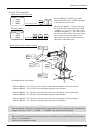
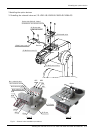
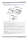
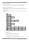
Fig.3-5 : Installing the hand output cable
1) Remove the hexagon socket bolts (five M4 x 10) and truss screw (three M3 x 8) that hold the No. 2 arm cover
B
<2>, and then remove both the No. 2 arm cover B <2>.
2) Remove the socket bolts <4> (four M4 x 8) that hold the No. 2 arm cover C <3> or the solenoid valves <5>,
and then remove the No. 2 arm cover C <3> or the solenoid valves <5>.
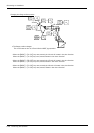
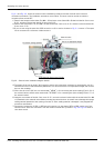
3) If you are not using the spare line (ADD: stored in a coil) in section A shown in Fig. 3-1, remove it. The spare
line is connected to a connector inside section A.
4) The hand output cable can be installed to both the No. 2 arm cover C <3> and the solenoid valves <5>.
However, if solenoid valves of three rows or more are used, it is not possible to install a hand output cable
separately because the hand output connectors (2 pcs.) in the forearm and the solenoid valves are already
connected.
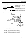
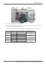
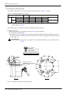
5) Remove one of the two grommets on either the No. 2 arm cover C <3> or the solenoid valves <5>. After
removing the grommet, peal off the sealing material left on the hole section of the plate.
6) After removing the lock nut attached to the hand output cable, feed the connector side of the hand output
cable (with a cable clamp) through the hole on the plate. Replace the removed lock nut in position and fasten
it securely.
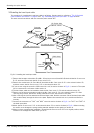
7) Connect the connectors of "GR1" and "GR2" stored in section A shown in Fig. 3-1 to "GR1" and "GR2" of
the hand output cable.
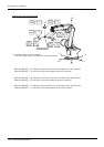
8) Mount the No. 2 arm cover C <3> or the solenoid valves <5> to section A shown in Fig. 3-1. When mounting,
be careful not to damage the sponge sealing material attached to the opening of section A.
9) When you have completed the installation, reinstall the No.2 arm cover B <2> to its original position, and be
careful not to entangle the cables when you do so.
DD
GR1 GR2
Grommet
Remove
Grommet
Remove
(M4×8, 4 bolts)
<4> Socket bolts
Plate
<5> Solenoid valves
<3> No. 2 arm cover C
Cable clamp
Lock nut
View D
Plate