


5-42
Maintenance and inspection procedures
5Maintenance and Inspection
5.3 Maintenance and inspection procedures
The procedures for carrying out the periodic maintenance and inspection are described in this section. Thoroughly
read the contents, and follow the instructions. This work can be commissioned to the Mitsubishi Service Depart
-
ment for a fee. (Never disassemble, etc., the parts not described in this manual.)
The maintenance parts, etc., required for the customer to carry out maintenance and inspection are described in
"5.4Maintenance parts" on page 52 of this manual. Always contact your dealer when parts are needed.
The origin of the machine system could deviate when this work is carried out.
"Review of the position data" and "re-teaching" will be required.
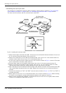
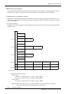
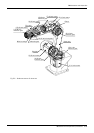
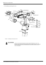
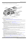
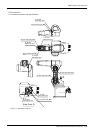
5.3.1 Robot arm structure
An outline structure drawing is shown in . Each part is as shown below.
1) The J1 axis rotation is driven by the J1 axis motor <1> and reduction gears <2> arranged in the base.
Non-excitation magnetic brakes are mounted in the J1axis motor <1>.
2) The J2 axis rotation is driven by the J2 axis motor <3> and reduction gears <4> arranged in the shoulder.
Non-excitation magnetic brakes are mounted in the J2 axis motor <3>.
3) The J3 axis rotation is driven by the J3 axis motor <5> and reduction gears <6> arranged in the shoulder.
Non-excitation magnetic brakes are mounted in the J3 axis motor <5>.
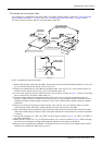
4) The J4 axis rotation is driven by the J4 axis motor <7> and reduction gears <8> arranged in the elbow block.
Non-excitation magnetic brakes are mounted in the J4 axis motor <7>.
5) The rotation of the J5 axis motor <9> arranged in the forearm is conveyed to the reduction gears <11> via
the timing belt <10> to rotate the wrist housing and following parts.
Non-excitation magnetic brakes are mounted in the J5 axis motor <9>.
6) The rotation of the J6 axis is driven by the J6 axis motor <12> arranged in the wrist housing and the reduc
-
tion gears <13>.
Non-excitation magnetic brakes are mounted in the J6 axis motor <12>.
CAUTION