


CRS-300 1:10 Redundancy Switch Revision 16
Cables and Connections MN/CRS300.IOM
4–42
4.6.3 Control Y-Cable Connections – CRS-300 to Modems
All traffic data configurations require the Control Y-Cable CA/WR12069-1, connected between
the CRS-300 RMI/TMI(s) and each CDM-Qx/QxL as follows:
• HD-15F connector labeled “J1” on the RMI or TMI(s), to
• DB-15M connectors labeled “Alarms” on each CDM-Qx/QxL modulator and
demodulator:
o J1 of the Control Y-Cable goes to the modulator Alarm connector.
o J2 of the Control Y-Cable goes to the demodulator Alarm connector.
4.6.4 Traffic Data Connections – CRS-300 to Modems
Connect and secure the cables between each CDM-Qx/QxL and the CRS-300 as follows:
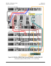
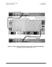
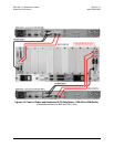
If EIA-530 V.35/EIA-232 is the traffic data type, refer to Figure 4-17 to connect and secure
the Control/Data Cable CA/WR0066 as follows:
• DB-25M connector labeled “P2” on the RMI or “P1” on the TMI(s), to
• DB-25F connector labeled “EIA-530” on the CDM-Qx/QxL demodulator.
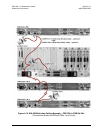
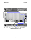
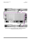
If Balanced G.703 is the traffic data type, refer to Figure 4-18 to connect and secure the Data
Cable CA/WR9038-6 as follows:
• DB-15M connector labeled “P1” on the RMI or TMI(s), to
• DB-15F connector labeled “G.703” on the CDM-Qx/QxL demodulator.
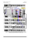
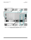
If Unbalanced G.703 is the traffic data type, refer to Figure 4-19 to first connect and secure
the 75Ω BNC Tx Cable CA/WR0813-8 as follows:
• BNC connector labeled “J4” on the RMI or “J3” on the TMI(s), to
• BNC connector labeled “Tx” on the demodulator.
Next, connect and secure the BNC Rx Cable CA/WR0813-8 as follows:
• BNC connector labeled “J3” on the RMI or “J5” on the TMI(s), to
• BNC connector labeled “Rx” on the demodulator.
If HSSI is the traffic data type, refer to Figure 4-20 to connect and secure the HSSI Data Cable
CA/WR9189-6 as follows:
• HSSI connector labeled “J2” on the RMI or “J3” on the TMI(s), to
• HSSI connector labeled “HSSI” on the demodulator.
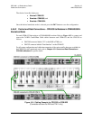
If Quad E1 is the traffic data type, refer to Figure 4-21 to first connect and secure the Quad E1
RMI Data Cable CA/WR13018 as follows:
• DB-15M connector labeled “P1” on the RMI, to
• (4X) RJ-48 connectors labeled “Port 1” through “Port 4” on the Redundant
CDM-Qx/QxL.