


CRS-300 1:10 Redundancy Switch Revision 16
Remote Control MN/CRS300.IOM
C–3
o To a local BUC or transceiver connected to a local modem;
o To a distant end BUC or transceiver through the distant end modem.
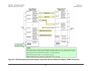
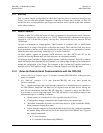
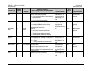
C.5 Packet Structure
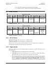
Controller-to-Target
Start of
Packet
Target
Address
Address
Delimiter
Instruction
Code
Code
Qualifier
Optional
Arguments
End of Packet
<
ASCII code 60
(1 character)
(4 characters)
/
ASCII code 47
(1 character)
(3 characters)
= or ?
ASCII codes
61 or 63
(1 character)
(n characters)
Carriage Return
ASCII code 13
(1 character)
Example: <0000/RSH=30[cr]
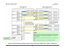
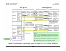
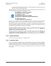
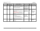
Target-to-Controller
Start of
Packet
Target
Address
Address
Delimiter
Instruction
Code
Code
Qualifier
Optional
Arguments
End of Packet
>
ASCII code 62
(1 character) (4 characters)
/
ASCII code 47
(1 character) (3 characters)
=, ?, !, or *
ASCII codes
61,63,33 or 42
(1 character)
(From 0 to n
characters)
Carriage Return,
Line Feed
ASCII codes
13,10
(2 characters)
Example: >0000/BBU=107[cr][lf]
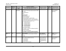
C.5.1 Start of Packet
Controller-to-Target: This is the character '<' (ASCII code 60)
Target-to-Controller: This is the character '>' (ASCII code 62)
Because this is used to provide a reliable indication of the start of packet, these two characters
may not appear anywhere else within the body of the message.
C.5.2 Target Address
While up to 9,999 devices can be uniquely addressed, connection to the CRS-300 imposes some
basic limitations:
• In EIA-232 applications, the Switch address is fixed at 0000.
• In EIA-485 applications, the Switch may be set to an address of 1000, 3000, 5000 or
7000. This allows up to four Switches to be connected on the same bus.
• The 11 modems that may be connected to the Switch may be accessed for remote monitor
& control through the Switch via virtual addresses. The details of this addressing scheme is
shown in Appendix B. ADDRESSING SCHEME INFORMATION. Valid remote
commands and queries that can be sent to the modems via the Switch depend upon the